Presented are two fan speed controllers for an RV air conditioner. These are designed to slow the speed of the blower motor to reduce noise and increase dehumidification.
The first, built in 2008, is entirely analog and built using discrete components. The second is an updated version using a DSP chip an featuring a PID control loop for accurate temperature control.
CAUTION! This project is presented in the interests of design study only. It will certainly void the warranty and may not represent a safe design. Circuitry such as this, attached to an AC source, is built at your own risk. Due to liability reasons, I will not built one for anyone – this is an advanced project for experimenters (I am putting it ‘out there’ as the circuitry, and the code, might be useful to others).
First Approach – A low-tech analog controller
In 2008 we bought a new 2008 Trail Sport travel trailer to replace our old destroyed 2004 Trail Lite. The only feature we really missed in our new RV was ducted air conditioning. It came down to an issue of money and weight: a unit with ducted air would have cost about $5000 more (since we’d have to order it) and would add over 500 pounds to the trailer’s weight. We opted for a unit on the lot which had a standard, roof-mounted, Carrier Air-V air conditioning unit.
The Air-V unit has an incredibly high volume fan (enough airflow to reach both ends of the trailer) but in doing so two undesirable effects reault: the first being the noise of the fan especially when trying to sleep and the second being that the evaporator coils do not run cold enough to dehumidify the air as well as our old RV unit (a Dometic) did. Both problems were solved by slowing the fan speed using a TRIAC based phase-angle controller.
Having the fan run continually, on very low speed, is desirable and fixes a problem with the original 2004 Trail Lite design in which that fan shut off completely when the compressor was off. This led to “stuffy” air in the unit in between compressor cycles which is completely avoided by having the fan run (so they had the right idea by leaving the fan running continually, the speed was simply too high).
While I could have opted for a high-tech design employing a DSP chip (as I used for other projects), for this project I decided to opt for a very low-tech approach using simple discrete components.
Resembling a light-dimmer, numerous designs were found in application notes from ST Microelectronics. The most useful note was AN308 covering TRIAC controls for inductive loads. Air conditioning units such as this use PSC (Permanent Split Capacitor) motors which are inductive and so require special circuit design to handle strange characteristics such as variable load impedance and phase differences between current and voltage.
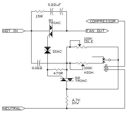 The best overall design uses two TRIACs to generate a train of triggering pulses which are completely symmetrical – important with a motor such as this – see the Application note, circuit 1.3 for a complete explanation of operation. I used two generic TRIACs similar to type C206D. A relay was used to switch the fan to a higher (but still less than full) speed when the compressor operates to avoid freezing-up of the evaporator coil. This is a relatively low-tech approach and a TRIAC opto-coupler could probably be used here. The circuit performs as per the app note and triggering pulses at 10KHz can be seen on an oscilloscope (this is a standard method of triggering thyristor devices for large industrial controls called a “picket fence”).
The circuit features a DIAC (a bilateral trigger diode) as well as a snubber (the 15 Ω resistor with two series 0.22μF capacitors).
In this simple version of the controller the voltage across the fan motor (as measured with a true-RMS meter) could be varied between 73VAC (representing about 60% of full output) and 123VAC (full) for the IDLE setting and between 102VAC (representing about 80%) and 123VAC for HIGH SPEED. The high-speed setting was purposely limited to prevent the evaporator coil from freezing-up due to lack of airflow (in which case the coil temperature falls below 0C casuing condensate to freeze solid and impede airflow completely). In operation, the fan speed is kept very low (and the unit very quiet) until the temperature increases inside the RV at which point the unit’s thermostat starts the compressor, the relay pull-in, and the fan speed increases. Obviously the unit is considerably louder when the compressor is running (with most of the noise from the fan) – using a sound-level meter the decrease in noise was approximately 6dB when the fan speed was reduced.
The entire circuit was built into a small plastic box and mounted on top of the air intake so that the speed adjustment potentiometers can be accessed simply by removing one air filter screen and inserting a small screwdriver. The controller was wired into the existing air conditioner via a harness of five wires and an inline Molex connector. Adding the circuit to the air conditioner unit requires breaking the connection between the main switch and the fan motor (all spade terminals), routing the output from the switch formerly to the fan motor to the Hot Input of the controller, tapping the AC Neutral, routing the Fan Output from the controller to the low speed fan wire, tapping the compressor ON signal (tapped after the thermostat in the unit), and of course adding a ground wire for safety. All metal parts in the controller including the heatsink for the TRIAC, are grounded.
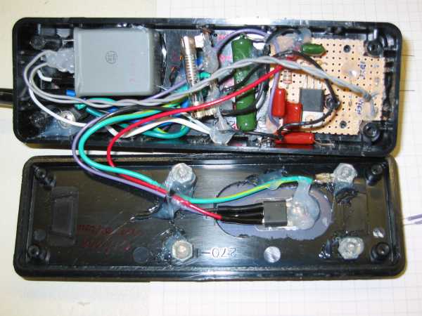 Construction is not critical however all components must be mounted to withstand vibration. The circuit was constructed on a small piece of perfboard as well as a single barrier strip inside the box. All components were potted, after assembly, using silicone rubber. The TRIAC was mounted on a small heatsink on top of the box (since it is in the air stream of the unit, it does not even get warm to the touch). Two screws protruding through the bottom of the box allow it to be mounted through two holes already in the intake.
While the controller as shown here works quite well at reducing fan noise, especially on IDLE mode (when the compressor is cycling off), the airflow on HIGH is still too high to allow adequate dehumidification of the inside air: frankly, on a very humid day the cooled air felt “damp”. Slowing the fan more with the compressor running risks freeze-up of the coils and so a sensor is required to increase fan speed should the evaporator coil fall below a preset lower limit. A thermistor was added which increases the fan speed to full when the evaporator temperature falls below 6C.
Second Approach – A high-tech DSP controller
In 2017 we traded in the Trail Sport for a Grand Design 2800BH. This unit came with ducted air (a Dometic unit). Like the old Carrier, the fan can be set to run continually (which we do to alleviate the ‘stuffiness’) and while the fan is quieter due to the ducted system (and even quieter after some modifications found on a camping board involving foam ducts to route the cold air as it exits the unit), the air still isn’t dehumidified as well as we’d like. On a hot day, for example, the evaporator hardly gets cold enough to condense water from the trailer – this is expected, as the air flow is large enough to limit the temperature difference between the intake and outlet of the unit to about 16C at best – by slowing the fan, the evaporator coils can be made much colder allowing condensation even at high inlet temperatures.
This time, a microcontroller was employed allowing implementation of a PID loop which will adjust the fan speed to precisely the value required to keep the evaporator at a set temperature: if the coils become too cold (and risk freezing), the fan speed will increase gradually until the target temp for the coils is reached. This approach should allow the airflow to be run as low as possible without allowing freeze-up.
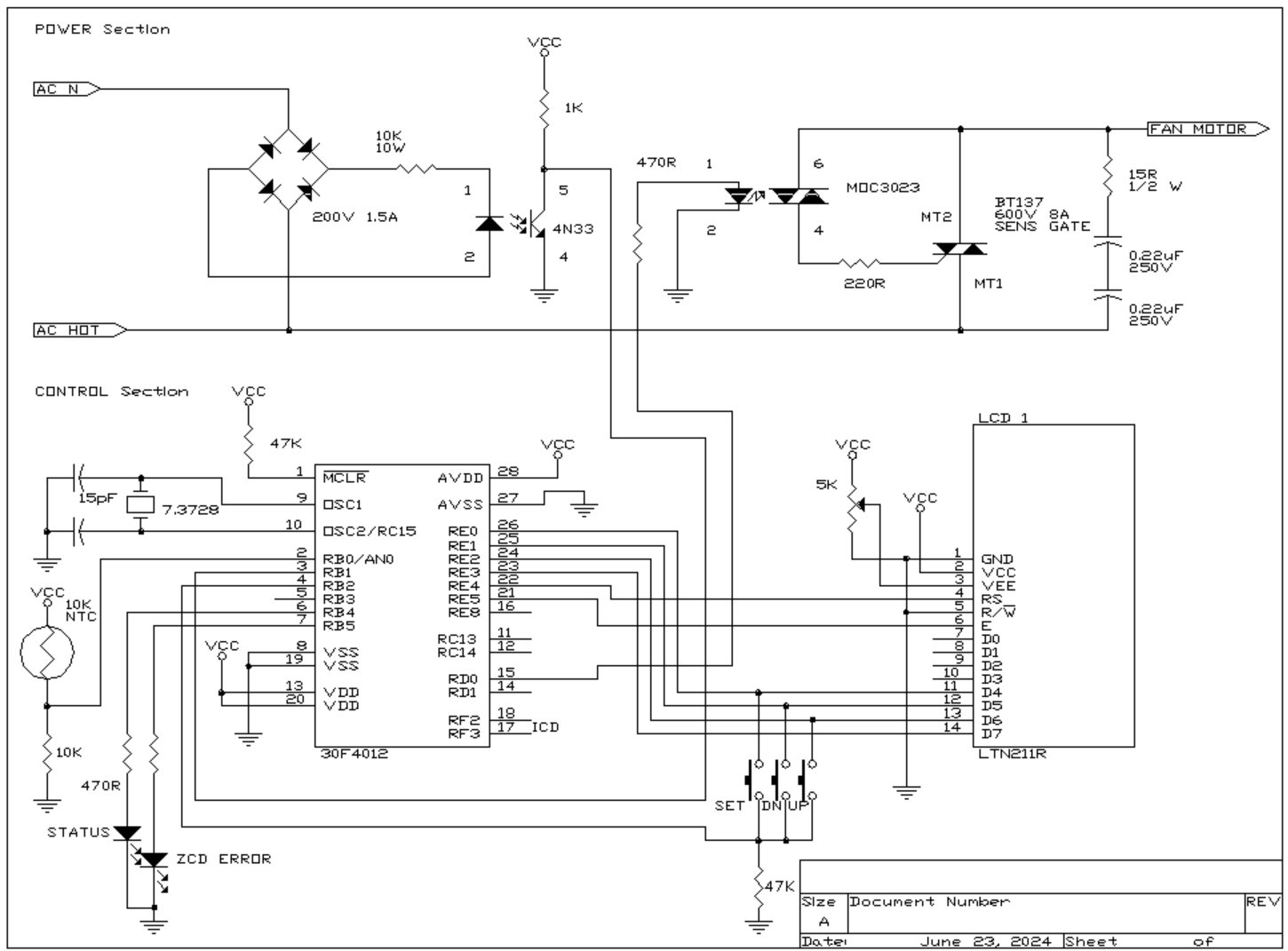
While any generic 8-bit MCU could likely be used, a PIC 16-bit DSP microcontroller was used here – specifically a dsPIC30F4012. Having a DSP core makes implementation of the PID loop easy (it has a true 32-bit hardware multiplier and two 40-bit accumulators useful to store the integral value) and this 28-pin chip has an on-chip 10-bit A/D (for temperature monitoring), data EEPROM (to store parameters such as loop gain), several timers (to implement the phase-angle controller) and runs at 5V.
Power Section
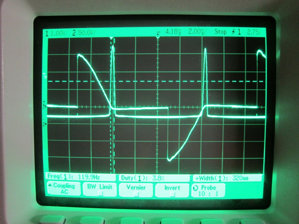 In order to implement a phase-angle controller the zero-cross of the AC line must be detected. A 4N33 opto-coupler is used here with a bridge rectifier and a large series resistor to prevent phase-shift which might otherwise occur. Pulses are produced at 120Hz and can be seen on the oscilloscope trace as a series of sharp high-going pulses.
The power-switching is done by a BT137 TRIAC connected via a MOC3023 opto-triac. The MOC3023 is a random-phase device which may be turned on at any point in the AC cycle … in the trace to the left it is switched at approximately the peak of the wave giving approximately 50% output. It is important that the waveform be symmetrical (although that is the task of the firmware involved).
In the chip, the phase controller is implemented using an interrupt when a zero-cross occurs and two timers which also generate interrupts: it is an autonomous section of code that runs on its own communicating with the main program via two registers (Phase Angle and an error status register). The first timer counts continually – the count representing a fraction of the angle of the wave – until the value of the timer matches the value in the PR1 register at which point the TRIAC is fired. The oscillator frequency of 7.3728MHz is increased to almost 120MHz by the internal x16 PLL – this gives a machine clock (Tcy) of 29.4912MHz (hence the 30 MIPs for the chip speed). For the timers, a prescaler divides by 256 to 115.2kHz so each 180 degree AC wave can be controlled within 0.1875 degrees (i.e. 960 discrete points per half-wave). “PhaseAngle”, the global variable which selects the firing point, updates PR1 and can assume a value between 1 (which would yield a full wave for maximum power) and 959 (which would yield almost zero power). Symmetry is important to avoid polarization of the motor and is ensured by updating the firing point only once per second (the PID loop delta-T).
A second timer waits 1/120th of a second (the time for a half-wave) for a zero cross to occur. Should a zero-cross be detected before the time expires, this timer is reset, however if the timer expires this signifies that a zero-cross was not detected within 1/120th of a second and so a fault is registered. This also halts the output immediately.
 Actual zero-cross is detected by a Change-Notification interrupt (like an interrupt, but triggered on both a high- and low-going edge). This will reset both timers – one (TMR2) so that the system knows if a fault occurs and the other (TMR1) to re-sync the phase-angle counter to the beginning of the cycle of the AC line. Since the zero-cross pulse has a finite width (measured at 320μs), the rising edge causes TRIAC shutdown (or at least turns off the opto-coupler so the TRIAC will stop conducting at the actual zero-cross) and the rising edge re-syncs the phase angle timer. The algorithm requires two successive zero-crosses to be detected before it flags that the ZCD is valid and output may proceed – this is done to ensure all zero crosses are detected and for symmetry of the final waveform.
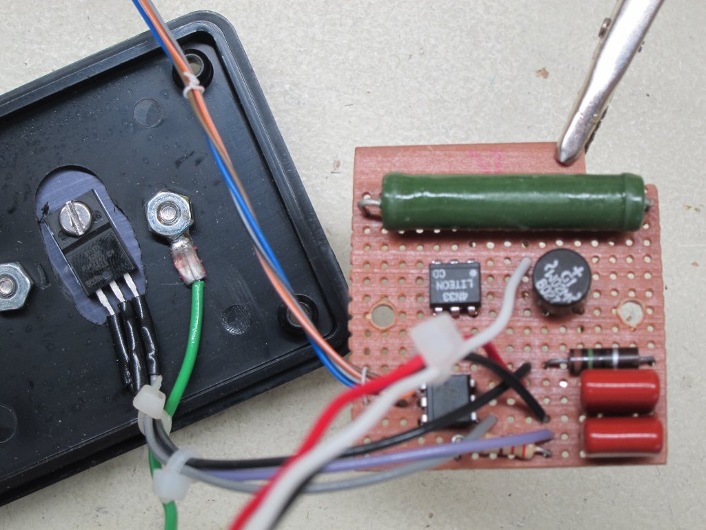
All power components are built on a separate small board as seen to the right. the entire rear of the board was covered in silicone after construction since the environment will be susceptible to vibration (in a towable RV) and loose AC wiring could be disastrous. The TRIAC is mounted on a small heatsink bolted to the cover of the enclosure – it need not be large as the device produces little heat and the actual heatsink is in the intake airflow for the unit.
Interesting note: this controller intercepts only the LOW fan winding however if the fan is powered on high, a voltage of about 160VAC appears on the low terminal since the fan itself acts as an autotransformer. This will result in the controller powering-up (but not driving the low winding) and so is harmless – it also means that all power components must withstand about 200VAC for safety. This ‘feature’ is useful to allow the controller to be powered without actually running the fan to set parameters initially (unless the programmer is set to exclude the EEPROM area).
PID Algorithm & Programming
For the most part, the actual phase-controller is interrupt-driven and hands-off once started. A global variable “PhaseAngle” is updated by the main program and used to set the output of the fan. The PI algorithm runs once per second as the process variable, the evaporator temperature, changes slowly. In fact, the derivative term was not implemented as it is hardly ever used in a (slow) thermal process.
The main PID loop begins by reading the analog voltage from a thermistor via the on-chip 10-bit ADC. Twenty readings are taken, added in the 40-bit DSP accumulator, and divided by 20 to get an average reading (this reduced noise). This analog reading is then converted to a temperature via a large 16-bit look-up table (originally generated via an Excel spreadsheet). Temperatures are stored as a x100 binary value. As an example, an ADC value of 0x01B1 returns a temperature of0x0731 or 1841 in decimal which represents 18.41 degrees-C. Internally, all values are stored as signed 16-bit numbers shifted two decimal places so a gain of 30 is stored as 3000 (0x0BB8). This makes display easy (by inserting a decimal point before the last two digits) as well as the math and gives decent resolution for parameters.
The error is now computed by subtracting the Set Point from this value – it is limited in range to +/- 1000 (decimal). The Proportional Term is computed first as a signed 16-bit number by multiplying the error times the P gain and dividing by 100 (since the gains are in units of x100). The chip has multiply and divide instructions making the code simple – as an example of how numbers are handled consider the code which calculates the P term:
   mov     Error,W1
   mov     P_Gain,W2
   mul.ss  w1,w2,w4    ;W4/w5 contain product

   mov     #100,w6
   repeat  #17
   div.sd  w4,w6       ;w0 contains quotient
   mov     w0,Proportional
Error is in units of 0.01C and P_Gain in units of x100. These two numbers are multiplied resulting in a 32-bit number (in two registers) which are then divided by 100. Multiplies and divides are done in the ALU for speed (the dsPIC has a rich set of math features). The maximum value of the P term, assuming error is capped at 10.00C and gain at 30.00, is 30000 which fits as a signed 16-bit number into a register.
Logic for calculating the Integral term consists mainly of code to prevent windup of the integrator. This term accumulates in one of the 40-bit accumulators on the chip however it can reach a large numerical value. To prevent ‘windup’ which results in large oscillations of the output term, the integrator only works where the I term can affect the output: when the fan speed is at minimum or maximum limits the integrator is held at the current value (there are a number of approaches to prevent windup of an integrator, this is only one). Logic is also provided to cap the integrator value to an arbitrary, but large, number.
The main program also updates an LCD, displaying current SP, PV (Evap Temp), and Fan Speed. Gain and other parameters are set using the LCD and pushbuttons to inc/dec each parameter. Parameters are stored in on-chip EEPROM and loaded when the chip is powered.
Some features in the original design were not required, for example the controller has a bypass relay which shuts-down the Dometic freeze-up sensor: originally it was thought that running the fan so low would result in an evaporator temperature which would prematurely trigger the freeze-up sensor but as it turns out, the fan must be at maximum output below 9C regardless so this feature is not required. The freeze-up sensor was seen to allow an evaporator temp of under 0C so it is not ‘too sensitive’ as originally thought. It is safer, regardless, to have the Dometic freeze-up sensor operating in the unlikely event of failure of the controller.
The version 1.2 code can be seen here (FanSpeed) – it is shown here as a text file but in reality is a “.s” file used with MPLAB-X.
Construction & Installation
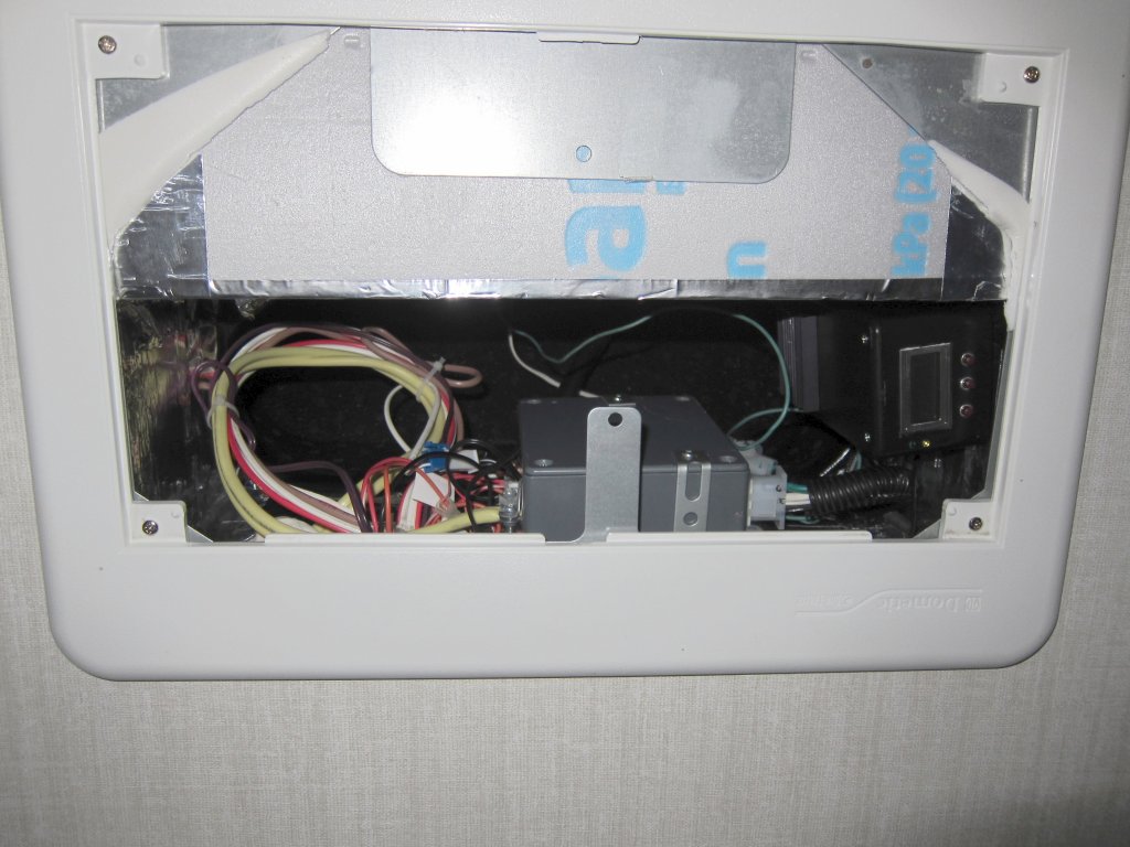
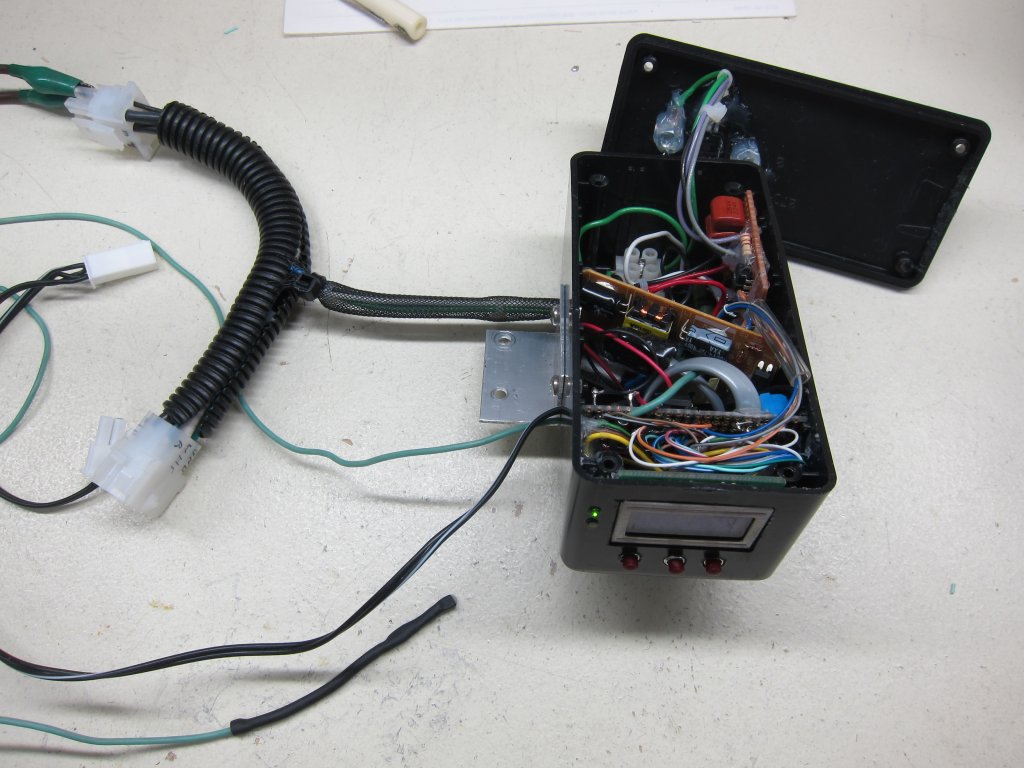
The entire controller is constructed into a small box which mounts beside the standard Dometic relay box. Molex connectors allow the unit to be connected without modification to the regular wiring.
The controller features a two-line by eight-character LCD display and three pushbuttons to set parameters (which are then stored in EEPROM). A small 5V supply (taken from an old USB adapter) is also contained in the box to power the circuit.
A PI controller requires tuning and this is easily done by pressing the SET pushbutton and cycling through parameters. It was found to operate reasonably well (and with a bit of an underdamped response) with a P gain of 1.5, an I gain of 0.12, a control gain of x16 (this is a “scaling factor” used when translating the sum of the P and I terms into a number representing phase angle), an SP of 10.00C, and the minimum fan speed 600/960. Too slow a minimum fan speed will run the risk of stalling the fan motor and overheating it – the controller also starts at maximum speed for three seconds to provide breakaway torque.
Operation and Observations
The controller works well enough, and one can observe it ‘homing in’ on the optimal fan speed to keep the evaporator temperature exact. With an SP=10.00C, the fan speed is seen to increase slowly as the evaporator temp falls below 10.00 – this is expected as the P gain is low and so the I term becomes more significant as the temperature stays below the SP. Around 9.0C the fan speed was seen to increase enough to raise the evaporator temp bringing it back up to 10C – this required a fan speed of about 67% of maximum. As air temperature in the unit cools, the evaporator temp will decrease and in turn, the fan speed will increase until it reaches maximum.
With out Dometic A/C, the unit works well enough during hot days and dehumidifies well – the air exiting from the vents is quite cool (measured at about 9C) and dry. Towels hung in the unit now dry in a few hours where they were previously still damp at night. At night, fan speed control is not useful as the fan speed increases naturally to maximum as the air in the unit approaches 18C (at an interior temp of 18C the evaporator was observed to reach a low of 3.5C at a fan speed was 100%) … reducing the fan speed at such low temperatures is not possible or freezing will likely occur. It was also found that at cool interior temperatures (< 21C) the fan speed ramped to maximum and yet the evaporator temp fell below 10C … this would have been the same case without the controller at all (and also explains why Dometic included the freeze sensor in their design).
So as far as noise reduction goes, it works during the day but at night the fan must run at full (low) speed regardless. The variation of the fan from idle speed to maximum was found objectionable at night as my wife prefers a constant noise – to make this possible, the LOW fan relay output was wired to this speed controller and the HIGH fan relay output was wired directly to the fan low winding. HIGH setting is now ‘constant low’ for night and LOW setting is now ‘dehumidify’ for the day.
Strange behaviour was seen as the phase angle lowers increasing power to the fan in the way of a non-linear relationship between fan power and fan rpm – at some point a small increase in power results in a large change in fan rpms causing a ‘surging’ of air which is precisely what the controller should prevent. It is strange but not overtly annoying and overall the controller meets the task of controlling fan speed to keep the evaporator temp constant.