I have three pinball machines: a 1980 Williams Firepower, a 1979 Stern Meteor, and a 1991 Data East Phantom of the Opera. All of my machines are digital, a technology I relate-to well since one of my hobbies is collecting vintage computers (frankly, I find working on microprocessor-based technology easier than electromechanical).
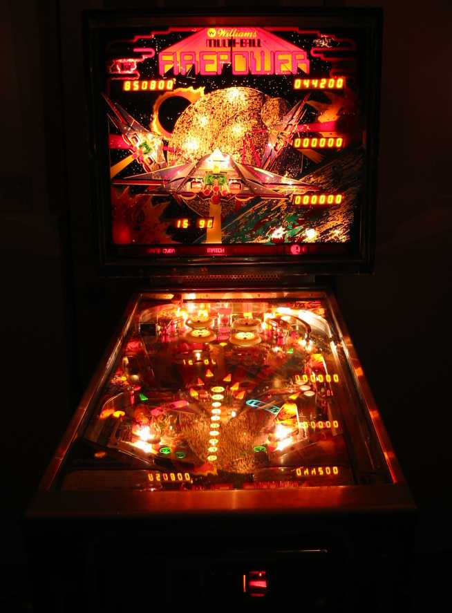
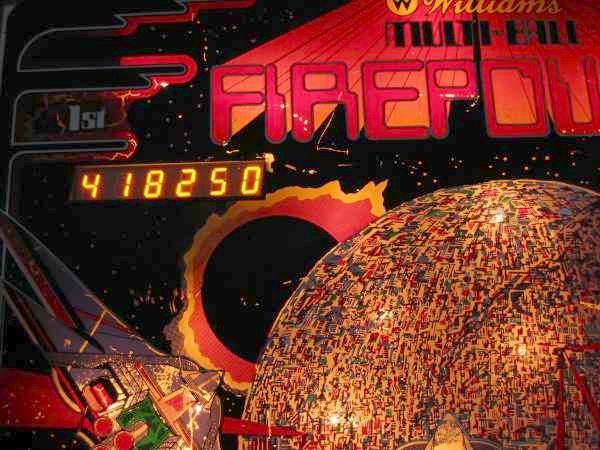
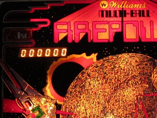
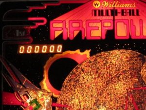
Most of this page describes my first machine, Firepower. As a teen, I played a great deal of pinball at the local roller rink – my favourite machine at the time being “Flash”, a Williams game circa 1979. This machine, Firepower, is just slightly newer, circa 1980, and was designed by the same guy who designed “Flash” (Steve Ritchie) – the two machines show a lot of similarities and it “just feels right” to play it! While the machine is electronic, it has many “old school” features including electromechanical flippers (with a dual-winding solenoid, no fancy drivers here), and very retro gas discharge displays for scoring.
 I bought it in 2009 and the condition of the machine was, well, “neglected” but you get what you pay for and it was cheap at $150! As we got it, the machine was dead (only a few backlights on the playfield and the backglass even worked and the game did not run – even “attract” mode would not run). The playfield was damaged by drywall screws put in to prevent the ball from rolling into the gutters as well as between the flippers. I figured the game would be a good bet for me since it features 1980’s computer technology (including the 6800 CPU) of which I’m familiar due to my hobby collecting old computers.
Well, a day of cleanup – both physical cleanup of the machine innards as well as contacts and connectors, repair of a driver board (which prevented a bunch of lights from working: hard to play when you can’t see which player is up), replacement of about twenty burned-out lamps, rebuilding of the wood backbox (one corner was split and an earlier attempt by a previous owner to repair it with nails failed) and the basic machine works! The entire family went on a pinball binge for a few days and we just love the beast!
The machine took a lot longer than a day, though, to bring “back to life”. The playfield required extensive touch-ups (outlined below on this page), the backglass was flaking, and many mechanical parts needed work (primarily a thorough cleanup), and the backbox needed to be rebuilt with wood filler after a dog apparently chewed the corner. Many little problems were fixed along the way including the ball ejector which “stuck” one out of every ten balls, a host of electronics issues including a strange bug which caused the machine to boot-up in audit mode, and “flaky” neon discharge displays which didn’t operate properly until the machine warms-up (it finally went dark completely).
This page chronicles the refurbishing process including hints and tips I’ve picked-up and even circuitry to replace unobtainable, obsolete driver chips.
The Issues
Here’s a list of repairs, upgrades, and modifications made. Each is listed on this page.
- Electronics repairs including:
- Repair of the driver board and connectors between the various PCBs
- Complete replacement of an unobtainable high-voltage driver chip
- Modification of the power supply to operate at lower voltages, and addition of a fan, to correct display issues
- Repair of the CPU board (CMOS battery and related parts)
- Repair of the Driver board (dead transistors, flaky 6821 PIA chips)
- Mechanical repairs to the jet bumpers
- The playfield required extensive work
- The cabinet, in poor mechanical and cosmetic shape, required repair
- The backglass required touch-ups
Electronics
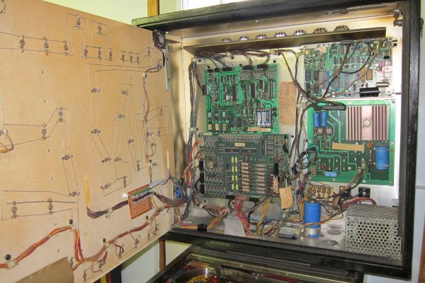
One of the intriguing things about this machine is the electronics. In the backbox are housed two boards with Motorola 6800 processors: one to run the game logic and a second to produce sound effects (including voice – one of the first machines to do so). The scoring displays are seven segment gas discharge displays similar to Nixie tubes. When we got the machine, it was not working, so …
The usual Culprits … Connectors
On arrival, the machine was dead. The displays would light-up and display cryptic codes (so the CPU was known to at least be running) but diagnostic codes were not accepted and the machine stayed in audit mode, showing ‘4971’ (the machine number) in the upper left display. After consulting a few web sites the CPU and I/O driver boards were carefully removed, all connectors cleaned with methyl hydrate, and reassembled with the problem solved! I expected to see more problems with the CPU boards (since being stuck in audit mode often means dreaded problems with the strange 5101 CMOS RAM chip housed in a weird 0.4″ 22-pin DIP package and almost unobtainable nowadays) but the Williams boards seem well-built – the connectors between the two main boards are the achilles heel, though, and known to be problematic on these machines. Even now, occasionally the machine ‘acts-up’ and requires re-seating of the connectors to scratch-off oxides and allow good contact once again.
… and the real Electronics problems
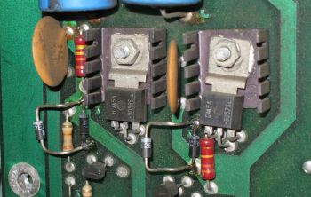
A second problem, manifested by the absence of two rows of lights (sixteen) on the playfield was found to be two resistors on the I/O board missing outright! It looks as if the resistors overheated and literally fell off the circuit board – they were nowhere to be found. Replacement with 27 ohm wirewound power resistors brought all light back to life.
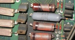 The grey resistor in the photo to the right is the replacement. Being larger than the original, one lead (on the right) was installed with heat-shrink tubing and bent under the package to mount it on the board. The original resistors show significant heat damage: this was a common problem with Williams driver boards. When replacing, use larger (5 watt) resistors to prevent a repeat issue.
Fixing the Displays
This machine uses seven-segment gas discharge displays called Panaplex displays similar to Nixies. It was hoped to keep the original displays rather than upgrade to newer LED displays as done to many machines when these displays fail.
This machines uses a Williams D8100 master display board driving five gas discharge 7-segment displays (one on the master display board itself – the credits/ball # display – and four player score displays on separate boards). The player 1 display has been problematic since the first day we got the machine – occasionally blinking and sometimes showing “888888” … then one day it, as well as the top two digits of the player 2 display, went dark. Looking at the schematics for the display board, all of the dark digits share a single UDN6184 driver chip for the anode (which operates at +100V). To absolutely prove that the chip was at fault (before replacement), a simple test was run in which a second 6184 chip (used to drive the player 3 and 4 displays) was temporarily jumped into the circuit to drive the first two displays. This simple test was done with IC-lead jumpers from the front of the board as follows:
- Remove connectors driving player 3 and 4 displays from the master display board (these are on top)
- Jumper IC11 (the suspected ‘dead’ 6184) pin 18 to IC12 (player 3/4 display) pin 18
The above jumper routes the 100000’s digit strobe (#1) to the player 1 display. The highest digit should now work (and will flip between “0” and the highest score digit on game-over mode). Other jumpers could be added as well (this also serves as a temporary fix allowing a two-player game while ordering parts):
- Jumper IC11 (the leftmost 6184) pin 17 to IC12 (middle 6184) pin 17
- Jumper IC11 (the leftmost 6184) pin 16 to IC12 (middle 6184) pin 16
- Jumper IC11 (the leftmost 6184) pin 15 to IC12 (middle 6184) pin 15
- Jumper IC11 (the leftmost 6184) pin 14 to IC12 (rightmost 6184) pin 18
- Jumper IC11 (the leftmost 6184) pin 13 to IC12 (rightmost 6184) pin 17
- Jumper IC11 (the leftmost 6184) pin 12 to IC12 (rightmost 6184) pin 16
- Jumper IC11 (the leftmost 6184) pin 11 to IC12 (rightmost 6184) pin 15
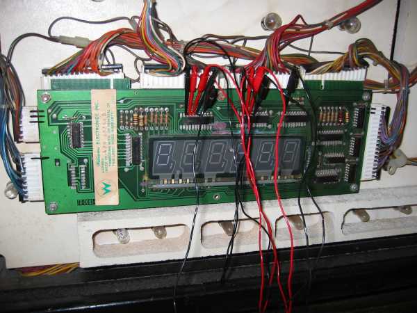 Remember to remove the player 3 and 4 connectors since a single 6184 cannot drive two displays (it lacks the current drive capability and so might well be blown). The jumpers can be seen in this photo and both player 1 and 2 displays will operate like this. WARNING: this assumes that the original 6184 failed “open” …. if for some reason the chip failed where the outputs are shorted to ground, the second 6184 may also blow … it might be prudent to check this using a VOM before trying this test.
Datasheets:
- UDN6184 Datasheet – the obsolete chip used to drive the anodes of the gas display.
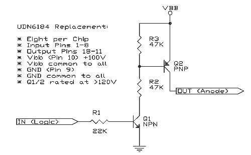 The UDN6184 driver is not attainable and was listed as ‘obsolete’ almost two decades ago so finding these is difficult. In order _not_ to destroy the master display board, the defective chip was carefully cut away (each pin was snipped from the IC package) and the old pins carefully removed. An 18-pin socket was then installed so that an original UDN6184 chip could be used (if ever obtained) or a replacement such as the small daughterboard I built using discrete components (basically, a board of discrete components which performs the exact same function as the original 6184 chip did and connected to the original 18-pin socket via a length of ribbon cable allowing mounting wherever there is room as seen in the photo. The circuit used is shown to the right and is duplicated eight times (the 6184 chip is an octal driver). It is a non-inverting high-side high voltage octal driver. Almost any high voltage transistors, with a VCE0 rating of over 120V can be used.
The circuit I have developed is a simple high-side driver. With a logic “0” input on R1, no current flows through Q1 and so the base of Q2 is pulled high via R3. With no base current flowing, Q2 is turned off and so the anode of the tube is not powered. With a logic “1” on the input, approximately 200μA of current flows through the base of Q1 (limited by R1, with a value chosen so that the input current is the same as the original 6184 chip rated input current). With Q1 on, a current of about 2mA (set by R2) flows through the base of Q2 turning it on and making the output (connected to the anode of the gas discharge tube) +100V causing segments of the tube to glow.
 In the first version, type 2SB1109 (PNP) and 2SD1609 (NPN) were used. These are driver transistors in a TO-126 package and can dissipate many watts of power – this is complete overkill however they were available in the junkbox and were one of the few transistors I found in the junkbox that had a high voltage rating (160V for these). A more suitable replacement is the TO-92 encased MPSA42 and MPSA92 transistors rated at 300V and a much lower current (gas discharge tubes do not require high current regardless) …. these parts are used in the Williams D8168 master display board which does not use 6184’s but instead uses discrete transistors for all drivers (both high side, like the 6184, as well as low side drivers for the cathodes). The fact that Williams made two master display boards for these systems likely means that they, too, had a problem finding these high voltage driver chips … even in those days. Use of these smaller TO-92 transistors (which are surprisingly inexpensive) would make the replacement board much smaller as well and so mounting would be easier.
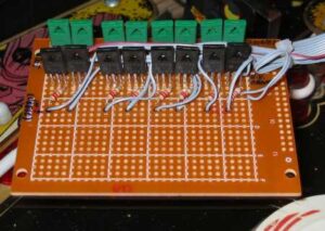
The prototype circuit seen here, built on a small piece of perfboard and connected to the socket on the display board via ribbon cable, is mounted on the backside of the display board.
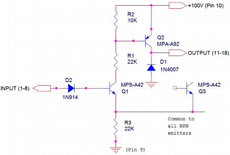
A newer replacement was finally made for the obsolete UDN6184 chip which features an integral 18-pin header and mounts directly onto the display board with no ribbon cable required. The new circuit uses MPS-A42 and MPS-A92 transistors as seen in the updated circuit to the right. Each of the eight channels consists of two transistors. The logic level input passes through diode D2 which serves to isolate the circuit in the event of failure so that the driver cannot be exposed to a high voltage. The NPN transistor is hence driven by the logic level input and provides current for the base of Q2 through R3 and R1 which limit this current. R3 is common to all eight channels since only one channel can be active at one time, and so this resistor serves as a master “brightness” setting (Q3, shown on the diagram, is from the next channel). Lower values of resistance will result in a brighter display, with a relatively high resistance (and hence low current) chosen here to lengthen the life of the display tubes.
R2 acts as a pull-up ensuring that Q2 is normally off. When Q1 conducts, current flows through R1 and R3 into the base of Q2 turning it on and providing +100V output for the display tube. Finally, diode D1 ensures negative voltage is not inadvertently applied to Q2 should the display tube short accidentally.
 A newer replacement was finally made for the obsolete UDN6184 chip which features an integral 18-pin header and mounts directly onto the display board with no ribbon cable required. The new circuit uses MPS-A42 and MPS-A92 transistors as seen in the updated circuit to the right. Each of the eight channels consists of two transistors. The logic level input passes through diode D2 which serves to isolate the circuit in the event of failure so that the driver cannot be exposed to a high voltage. The NPN transistor is hence driven by the logic level input and provides current for the base of Q2 through R3 and R1 which limit this current. R3 is common to all eight channels since only one channel can be active at one time, and so this resistor serves as a master “brightness” setting (Q3, shown on the diagram, is from the next channel). Lower values of resistance will result in a brighter display, with a relatively high resistance (and hence low current) chosen here to lengthen the life of the display tubes.
R2 acts as a pull-up ensuring that Q2 is normally off. When Q1 conducts, current flows through R1 and R3 into the base of Q2 turning it on and providing +100V output for the display tube. Finally, diode D1 ensures negative voltage is not inadvertently applied to Q2 should the display tube short accidentally.
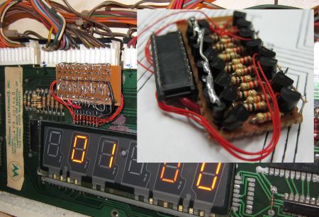 The new UDN6184 replacement is seen here in use mounted on the master display board, with an inset detailing the circuit as mounted on the perf-board. It was required that the circuit be as flat as possible in order to allow mounting in the thin space between the backglass and the display board so components are mounted as close as possible to the board. The 1N4007 diodes were mounted on their end with one lead also acting as the connection to the header leads. Transistors were mounted close to the board and resistors were laid-out for minimum height. The resulting assembly is a small board 1.6″ wide by 0.9″ mounted to one side of the header such that it does not interfere with the glass display tube (on one side) or edge connector (on the other) as seen in the photo.
Prolonging Display Life
 Even after repair, the displays would occasionally get “fuzzy” meaning they exhibit a dull, diffused glow on all segments even when they should be dark. I have seen this effect before with 74141 drivers when building a Nixie Thermostat and so the fix was to simply lower the high voltage used to drive the tubes from the factory setting of +/- 100V to +/- 91V (a 9% reduction). This was accomplished by adding a 1N5270 91V zener diode directly across the existing 100V diode (two are required since this is a bipolar supply). This will also, logically, prolong the life of the display tubes.
 Finally, a small computer-type fan was added to the upper-left corner of the display board to assist air circulation between the glass and the displays removing heat from the lamps (which were all replaced with lower-current versions of the originals to both reduce heat and make defects in the backglass less noticeable). Power was taken from the +18V lighting circuit (blue and black wires) which feeds the 12V fan via a 150Ω series resistance
BOARD FIXES
Early on, a few simple fixes were made to the driver board including replacing resistors that had apparently melted off the board. The game played OK for many years but sixteen years later it developed several weird problems including:
- Booting to diagnostic mode (normal when sensors stick, but happening for no reason)
- A ball was kicked into the shooting lane on every power-up
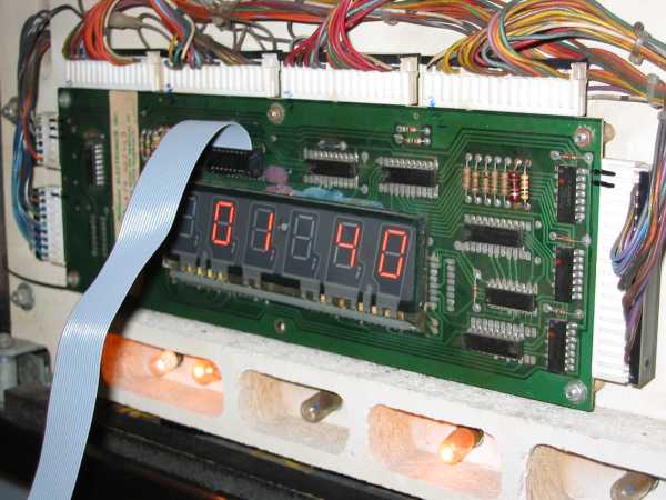
- The display showing only every other digit (so that the ‘player one’ display would show ‘_ 5 _ 0 _ 0’ instead of ‘550000’ as expected).
The CPU board was tackled first. The CMOS RAM batteries were fresh, but TP7 showed 6.35V (!). Turned out the PCB had faulty traces between the battery terminals and traces on the bottom of the board. The old battery holder was removed (I should have done that sixteen years ago), replaced with a new one, and traces were re-soldered. The board passed diagnostics (two blinks of the LEDs) so luckily the 5101 RAM chip survived. In addition D17, a 1N914 diode to isolate the batteries, was found shorted and hence replaced.
With the displays acting weird, the 6820 PIA was unsoldered, a 40-pin socket installed on the board, and a newer 6821 installed. This wasn’t the problem, but was probably prudent regardless given the propensity of the 6820’s to fail. As well, all pins were re-soldered since the power rails showed only 4.77V at the chips – they now showed 5.03V so there was another potential problem headed-off. The only pins that had bad solder connections were those which connected to the thick ground traces on the board – a LOT of heat was required to re-solder these (a 100W Weller gun was used instead of my usual Haako soldering station).
Next, Driver board was examined. Several TIP122 transistors were replaced (one a bad previous fix with bad soldering and two broke off the board during handling) and a pin on the intra-board connector was missing as well and repaired. During bench testing the 7408 AND gates used for blanking protection were tested and were fine but some output lines on the uninitialized PIA chips were logic low when they should have been high-Z inputs. On the advice of a YouTube video, all three 6821 PIA chips were replaced – each was desoldered, a socket installed on the board, and a new 6821 (I have spares for my vintage Ohio Scientific computer collection) put in. Surprisingly, and NOT intuitively, replacement of the PIAs on the driver board solved the display problem on the CPU board as well as the solenoid firing issue. The displays also seem more stable and don’t ‘blink-out’ periodically like they did: likely the 6821’s have been causing trouble for some time.
Mechanicals
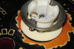 An old machine like this is plagued with a host of mechanical problems, most repairable without resorting to complete replacement. An example was the four jet or “mushroom” bumpers. From the time we acquired the machine they were never quite “right”: a few of these bumpers had circular rings that were loose and one had the ring tilted about 10 degrees downward. After some consideration, all four were removed, the pushrods extending below the playfield removed from the rings, and the assembly welded with a small MIG welder making the entire unit solid. Originally, the rods were connected to the circular rings with a peen. This was ground off – several were loose or already disconnected – and rod welded directly to the ring. The weld was then ground-down removing splatter (my MIG is a flux-core and so my welds are hardly “clean”, but they are strong). One of the rods also had a broken threaded end: that rod was drilled-out and a threaded rod inserted and welded onto the end of the rod. This entire fix was a huge improvement in the operation of the bumpers which are now incredibly solid and hit the ball much harder than before! It was a cheaper alternative than purchasing replacement parts (ring and rod assemblies) which sell for under $10 each, but it did consume a total of four hours to rebuild the bumpers. Such is the nature of a hobby though!
Apparent on the bumper as well as on the plastic protector on the playfield are weld splatters. There were caused by a previous butcher, not me! Apparently, during a previous fix, the rods were welded to the ring in-spot (ouch) with weld splatters damaging these components. Aside from damage to these parts, the previous welds were inferior and many were fractured. All old welds were ground-off and all were re-welded properly (i.e. in a workshop, where they could be done properly).
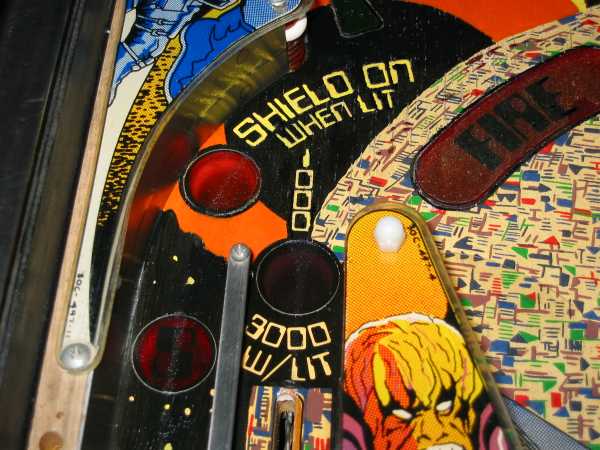
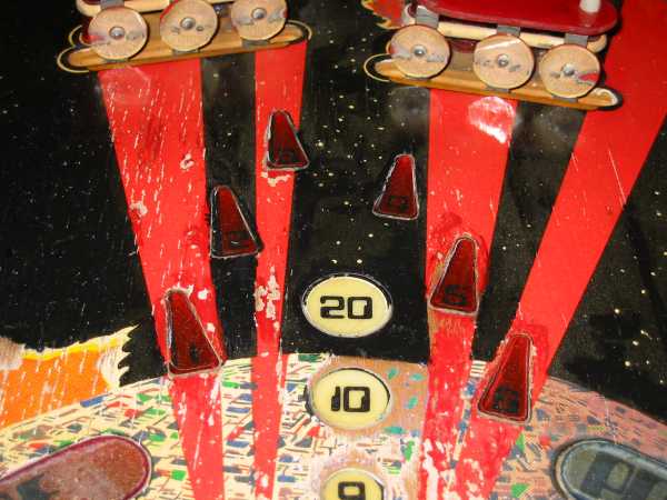
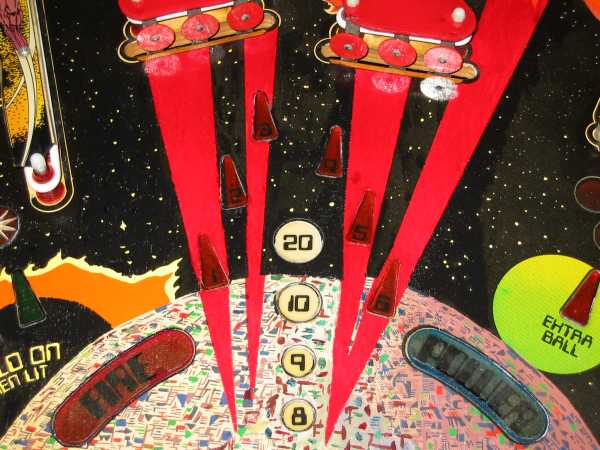
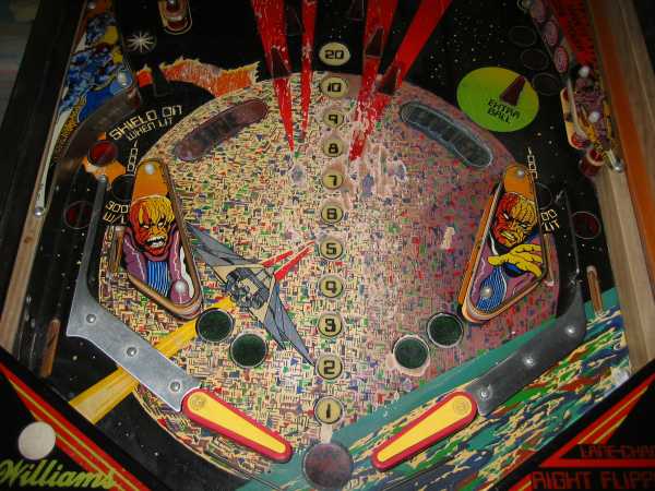
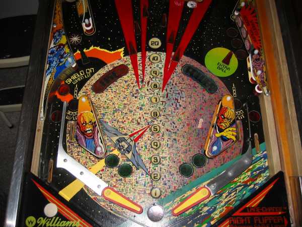
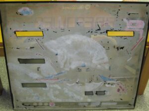
Refurbishing the Playfield
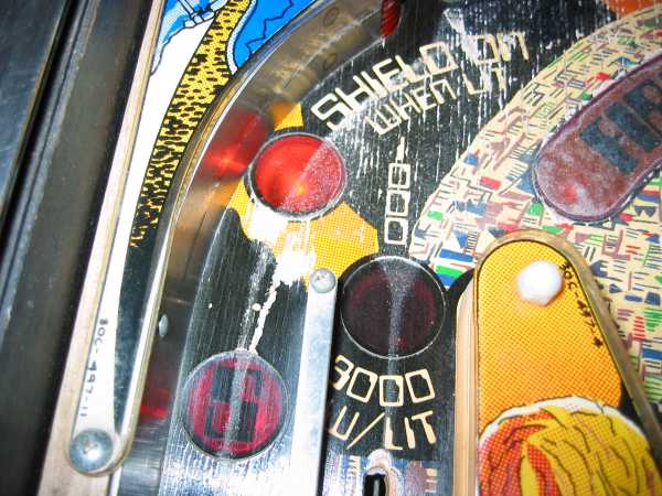
Overall, the playfield required the most attention since this affects playability. As purchased, the playfield was in a “badly neglected” state with paint peeling or missing in many places. Some spots were worn with base wood visible (not bad) while other areas featured peeling paint in lines along the grain (much worse), the later problem being worse since the ridges formed by the peeling paint would change the trajectory of the ball itself. There are a host of opinions from various people and sites: to touch-up or not to touch-up. Figuring that “the playfield can’t get much worse” I decided to opt for repainting the playfield. Various media were tested, experimentally, on the playfield. While artists oil paints allowed the best colour matching they did not present a hard surface and would “track” as the ball rolls over. Glass stain (purchased originally to repair the backglass) were also tried but the coating was not opaque enough to cover-up blemishes. Finally, I settled on high gloss acrylic paints. These are inexpensive, readily available (in Canada at Wal-Mart), clean-up with water when wet, and have a high-gloss surface when dry over which the ball rolls quite nicely without tracking or excessive wear. The paint used were Folkart/Plaid brand “Shiny” acrylics #2715 Licorice, #2702 Engine Red, and #2706 Lemon Custard (with colours approximating the originals). Finally, a coat of polyurethane (#882) was applied instead of wax (I wanted to hold-off on the use of wax until I was positive I would not do any more touch-ups on the playfield). I have never actually waxed the playfield: I simply give it a new coat of polyurethane every six to nine months after a quick cleaning. NOTE: only use water-based cleaners to prepare the playfield for a new coat of polyurethane, never use methy alcohol to clean the playfield as it will result in a cloudy surface.
The following sections detail repairs made to the playfield and feature “before” and “after” photos of the same area to show how the repair went. I am not an artist by an by means although, being a hobby project, I do have patience (required when painting areas like this with a tiny brush).
Playfield Photos: Before and After …
Cabinet
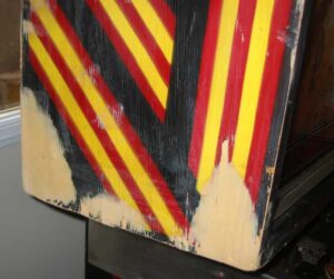 As received the outside cabinet was in rough shape. The backbox itself had one broken corner (with the wood completely separated), and many chunks were taken out of the unit, apparently from a large dog!
Once cleaned (requiring over a litre of “Mean Green” cleaner), the corner of the backbox was separated, grooves cleaned, and reassembled with carpenter’s glue and wood screws. After rebuilding, this corner, as well as most others – in most cases two plys of wood were missing – was done with wood filler to build-up missing wood and form square corners which were sanded to make square edges. The cabinet was then painted with the same acrylic paint used on the playfield.
The backbox after wood filler but before painting. The size of the repair can be seen in this photo but not the depth: two or more layers of ply were completely missing from these areas. In addition to this area (the worst), there were many gouges in the cabinet which required filling.
Backglass
 The backglass on the machine was flaking badly but much of the intricate pattern was still intact. In order to preserve it, it was sprayed with lacquer. Prior to sealing, it was hoped to clean the glass but any attempt to touch or wipe it caused more paint to flake so lacquer was applied to the uncleaned surface (only the clear windows for the displays were cleaned). The first layer of lacquer was sprayed onto the glass from a height of 50cm to avoid direct spray which might blow flakes around … subsequent layers were applied directly. The backglass could then be handled for touch-ups.
Links
- Fred’s Pinball Station with a good description on playfield repair
- Mark’s Pinball Page with a great set of troubleshooting guides for Williams machines
- Restoring Pinball and Arcade Games a lot of basic info on restoration