I have always had a thing for lasers – most of my 29-year career as a professor involved teaching lasers in Niagara College’s photonics programs – however I had been building lasers far before that, as I built many for science fair projects while in high school. This page outlines several of the lasers I’ve built over the years both for science fair projects in the 80’s and in labs at the college during my time as a professor. (The lasers presented here are a selection of those from my old ‘homebuilt lasers’ web site).
WARNING: Construction and operation of any laser device is hazardous. Do not attempt to construct or operate a laser without adequate safeguards and safety practices. Most lasers involve high voltages, toxic chemicals, high vacuum, laser radiation and other hazards. The author specifically disclaims any and all liabilities associated with the construction and use of such devices. Designs presented here are in the interests of providing information on operational principles only and do not represent safe nor ANSI safety compliant designs.
Nitrogen (Low Pressure) Lasers
This laser produces intense, short, pulses of UV radiation at 337.1nm and is useful for applications ranging from exciting fluorescence in materials to pumping dye lasers. This is one of the easiest gas lasers to build ‘from scratch’ (and one which has great utility) although the electrical discharge circuitry must be carefully designed. While the average power output will be under 10mW, the peak power of the UV output pulses will be on the order of 100’s of kilowatts (owing to the short pulse length).
Abstract
The nitrogen laser described is a low-pressure design and requires a vacuum pump. It produces a pulse of 5 to 10nS in duration which has a beam cross-section of about 10mm by 2mm. The power output and beam shape lend themselves well to pumping a dye laser. A second approach (outlined further on this page) is a TEA version of the nitrogen laser. TEA lasers (for Transverse Electrical-discharge at Atmospheric pressure) do not require a vacuum system at all as they operate at atmospheric (or greater) pressures. The TEA approach, however is ‘touchier’ and requires very careful construction.
Introduction
The laser described is a ‘normal’ (i.e., low-pressure) design and is a better bet for construction and utility than TEA lasers. Likely the easiest of all lasers to construct, this pulsed gas laser produces an ultraviolet laser beam at 337.1 nm. Pulses from this laser last 5-10 ns. The laser itself consists of a simple laser tube with long transverse (parallel to the tube) electrodes and high-voltage capacitors usually made of dual-sided printed circuit board. Expensive optics are not required (it will usually lase without mirrors at all) since the laser operates superradiantly due to its enormous gain! This design is quite ‘forgiving’ in construction (except for the choice of PCB for the capacitors). From the constructor’s point of view, the only additional equipment required is a vacuum pump and even that need not be expensive as only a moderate vacuum of 25 torr is required (an inexpensive pump will work well and even an old compressor from a refrigerator will suffice to pull a vacuum at this level). If built well, this laser will also operate using regular air (which is 78% nitrogen) but at reduced power outputs.
This design uses a Blumlein / transmission line arrangement similar to that described by James Small in The Amateur Scientist[1][2]. An improved second laser utilizes a laser tube 30cm long, made from milled plexiglas. Capacitors are fabricated from thin (0.020″) printed circuit board etched to form two capacitors. The laser operates on either pure nitrogen gas or plain air (both flowing gas) at pressures ranging from 25 to 75 torr. Using plain air as a lasant it was observed that pulse repeatability is poor (about 50% of pulses fail to lase) and asymmetric beam distribution – where the beam was concentrated towards the spark-gap side transverse electrode – was observed, especially at higher than normal operating pressures. With pure nitrogen as a lasant performance was excellent as was shot repeatability and output power was also increased four to five-fold over the use of air. The laser operates at 10kV to 15kV with a maximum voltage of 20kV set by the breakdown limit of the epoxy/glass dielectric employed. The laser, with high peak powers and a 1 cm wide beam, makes an excellent pump source for dye lasers or for exciting fluorescence in materials.
Basic Nitrogen Laser Structure
The laser tube itself [1][2][7] consists of a housing containing two transverse, flat electrodes parallel to the output beam. A suitable tube may be fashioned from two strips of thin copper or brass shim stock 30cm long cemented with epoxy into a split black ABS sewer pipe or two plexiglass slabs acting as a vacuum housing. Capacitors may be made of either dual-sided PC board etched to form two capacitors or fabricated from aluminum foil and plastic sheets. The critical factor in the construction of this laser is minimizing inductance in the discharge path to generate the incredibly fast pulse needed for laser action to occur. The self-inductance of a capacitor of this type is linearly proportional to the thickness of the dielectric [6] and so keeping the dielectric thin keeps the discharge fast. In my original laser I used very thin PC board (0.015″) for the capacitors as it has a higher capacitance (and hence energy storage) as well as lower inductance (and hence faster discharge) than normal PC board (which is 0.045″ thick). I have tried, and failed, to use thicker board myself and have heard from a number af amateurs who have also tried the same but no one seems to be able to make thicker board work. Be sure, then, to obtain the proper (0.015″ or 0.020″ thick) board or make your own capacitors from flat plates and sheets of dielectric (there are numerous other amateur designs on the web demonstrating the construction of capacitors from aluminum foil and plastic film).
The laser gain is extraordinarily high, so much so that a single pass of light down the laser tube amplifies radiation enough to produce a powerful output beam. No mirrors are required for this laser – this is what is called a superradiant laser. The output beam simply passes through a thin glass microscope slide to exit the laser tube. This also eliminates mirror alignment problems which plague homebrew laser builders (and professionals alike) with most other types of lasers. The addition of a rear mirror will, however, boost power over 250%. In my case I’ve used simple, inexpensive, first-surface mirrors inside the vacuum housing of my first laser itself as a rear reflector with good success. If you put the mirror inside the vacuum housing like I did be sure to have adjustment screws on the mirror which are accessible outside the vacuum housing so that it may be aligned properly.
A high vacuum is not required for this type of laser: a vacuum of 25 to 75 torr is sufficient. This is easily produced from an old sealed refrigerator compressor used in reverse. In the past I have acquired compressors from scrap yards which work well for this purpose. Choose a compressor from a small fridge which has only two metal lines (intake and output) and be sure to scavenge the start relay as well (usually mounted on the side of the compressor itself). Carefully cut the lines to release pressure (these days the refrigerant gas is usually already removed for environmental reasons) before cutting the lines. Leave 10cm of line protruding from the compressor to allow attachment of rubber tubing. The only concern with these compressors is the probability of oil contamination as refrigerant oil is backstreamed into the laser – if possible, obtain a single-stage vacuum pump as these do not have the same issues, otherwise consider a trap to minimize backstreamed oil vapour from entering the laser channel which will necessitate periodic cleaning of windows.
These lasers are usually supplied with flowing nitrogen gas from a compressed gas tank. Air, which is 78% nitrogen anyway, may be used if the laser has been built well and has enough optical gain but this will reduce the output power about five-fold (as well as reduce beam quality – see notes below). Standard-grade nitrogen of the type used by welders is quite suitable for this laser so more expensive high-purity gas is of little benefit. An oxygen regulator of the type used by welders can be used if an adapter from a nitrogen-bottle fitting to an oxygen-regulator fitting is used (I did this years ago. It worked well and was quite inexpensive). The output from the regulator is set to less than 5 psi and a needle valve is used to regulate gas flow through the laser tube. Pressure is regulated in this manner: the vacuum pump is connected directly to one port of the laser tube, and the inflow of gas regulated by the needle valve to control tube pressure. Another inexpensive option is the use of liquid nitrogen as a gas source. This is fine for short term operation but tends to boil off quickly whether being used or not.
To begin, see the [2] Scientific American Article in the June 1974 edition in the Amateur Scientist column which describes an easily constructed laser of this type. This article is also contained on the CD compilation of the Amateur Scientist available on the web. This is required reading before attempting to construct such a laser.
Important Principles Of Operation
The design of this laser is obviously not like other gas lasers such as the ubiquitous HeNe. The sole purpose of the two-capacitor Blumlein switch arrangement and transverse electrodes is to dump energy into the lasing volume in an incredibly short time frame.
By now you should understand population inversion (If not, start with a good basic reference [8]). To maintain lasing action there must be a higher population of the active medium (nitrogen gas molecules in this case) at the upper lasing level than at the lower level. The problem here is the lifetime of these levels: the upper level (at about 9eV) has a very short lifetime of about 20 nSec [3] while the lower lasing level (at about 6eV) has a much longer lifetime of 10mSec. The only way to get lasing action to occur is to quickly populate the upper level ensuring population inversion occurs [8]. This is done by a massive electrical pulse where electron collisions cause the preferential population of the upper energy band first (Were it not for this effect of being able to pump the upper energy level first, this laser would not work at all). After about 20nSec though this population of molecules at the ULL will decay to the lower level (a metastable state) where it will stay and so lasing action will quickly cease after the electrical pulse. Nitrogen lasers are hence self terminating in the same manner as the pure neon laser (operating at 540.1nm). To make matters worse Nitrogen molecules at the lower state absorb UV light strongly. The pulse length of the low-pressure Nitrogen laser, then, is limited to about 20nS (the point where population inversion is no longer possible since half of the molecules in the upper energy state have decayed to the lower state) and likely somewhat shorter than that since the ULL lifetime is, by definition, the point where 50% of the excited molecules will decay to a lower energy state – at some point before that time has expired lasing action will terminate – the ULL will decay to the point where the inversion DN is insufficient to generate enough gain to overcome losses in the laser. Incidentally, the lifetime of the upper-lasing level is dependent on the pressure in the laser tube. As pressure rises, the lifetime shortens [3] according to:
This behaviour is an important factor in the design of a TEA nitrogen laser where the pressure is 760 torr (one atmosphere) and so the lifetime is about 2ns. In a low-pressure laser like this one, the lifetime of about 20ns relaxes the need for extreme discharge speed (meaning a Blumlein transmission line which is not completely optimal will still work).
Being a molecular laser, in which the active species is the N2 molecule, energy levels (ULL and LLL) are vibronic levels and are defined by both electron energy state as well as vibrational energies. Because multiple closely-spaced energy levels define each band (the ULL and the LLL), this leads to a relatively large spectral bandwidth for this laser’s output of about 0.1nm. Since the laser is superradiant, wavelength selection is ineffectual.
The time scales involved should bring to light the importance of a very low inductance discharge path for currents in the laser. Any stray inductance (including the self-inductance of the capacitors and inductance of the spark gap itself [4]) will slow the discharge time and hence stop lasing action. The discharge must proceed in considerably less time than the ULL lifetime to ensure efficient pumping. Capacitors must be very low inductance indeed. In epoxy-glass PCB material, inductance increases as thickness of the dielectric [6] so the thinnest possible material must be used. If 0.015″ PCB is used the inductance will be low enough to allow the laser to work but the board will only take 1kV per 0.001″ of dielectric thickness so the capacitors can be run at a maximum of about 15kV. If 0.015″ (or 0.020″ at thickest) PCB is unavailable, the next best option is likely to fabricate capacitors using flat metal plates or foil and thin dielectric. This arrangement also allows for changing the dielectric should it fail due to the high voltages across it (which _does_ happen with dull regularity): A number of amateur laser enthusiasts have successfully done this.
Of course the Blumlein/Transverse electrode arrangement is not the only one which will work [5] but it is the most efficient at pumping the entire lasing volume in the shortest possible time. Among other things, a fast risetime discharge inhibits arc formation in the discharge and instead encourages a voluminous “spread-out” discharge between the electrodes – required for laser gain. Nitrogen lasers belong to a class of lasers called self-terminating lasers which include several other gases and many metal vapours. Other self-terminating lasers such as the copper-vapour laser have much longer upper-energy level lifetimes so the time for discharge in those lasers can be much longer. Copper-vapour lasers usually do not use the transverse electrode arrangement. Still other self-terminaing lasers such as Neon with a green output at 540.1nm have shorter upper-level lifetimes so their discharges must be even faster than that used for Nitrogen (1.5nS as opposed to 10nS).
Finally, the E/p ratio (the ratio of the electric field to pressure) of the gas must be considered. Nitrogen lasers have been reported to operate over a wide range of E/p values however it is generally acknowledged that the optimal E/p is around 120 to 150 V/cm-torr. For a low-pressure design with a 1cm gap and an operating voltage of 15kV, the optimal gas pressure should be around 100 torr. Observations made using these two lasers show a higher operating E/P of 160 to 360 V/cm-torr.
Low Pressure Laser: First Design (Circa 1983)
My original Nitrogen laser, built in 1983 and used exclusively as a ‘pump’ for a dye laser (see my science page on this site for details), was fashioned after the design by Jam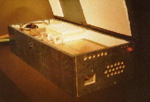 es G. Small which appears in Scientific American [2] (Indeed, it was designed, essentially, by Small during a private talk in Albuquerque NM in 1983). In my laser I used two thin (0.015″) dual-sided printed circuit boards as capacitors. Ordinary PC board used for circuits is much thicker and will not work for a laser of this type since it’s self-inductance is too high which leads to a slow discharge (Discharge times must be under 10nS for this laser to work). It would have been possible to fabricate a capacitor from of plates of copper or aluminum with a mylar (drafting film) dielectric but the PC Board certainly simplifies construction. PCB this thin is difficult to obtain and I was lucky to find it at Active Surplus on Queen St. in Toronto. Each board was about 15cm by 30cm with the 30cm side being parallel to the tube. The lower plate of each capacitor was connected together via a piece of copper. The upper plates, on the top and bottom of the entire assembly, were soldered to the tube electrodes and a spark gap was soldered to the top capacitor.
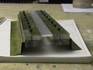
The insides of the entire laser are pictured here. The electrodes of this laser were simply made of single-sided PC board which were soldered to the capacitors along 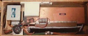 their entire length for good connection. The electrodes (single sided) protruded into the vacuum enclosure which was made of a 1.5 inch piece of black ABS drain pipe (DVW) split down the centre. The entire tube was held together with epoxy cement. The rear of the tube contained a first-surface mirror right inside the tube itself with adjustment screws protruding from the rear. The front of the tube was cut at the Brewster angle for 337.1 nm and sealed with a piece of plexiglas. The laser beam exited the tube through a hole in the plexi covered with a quartz microscope slide acing as a window (UV does not pass through plexi so a window is required). Additional sealing of the tube was accomplished using melted vacuum wax.
This laser used flowing nitrogen gas both as coolant and to purge the tube of leaked and evolved gases. As I recall there were a number of leaks in the tube but this hardly affected power output as the purity of the lasing gas was not all that critical. Nitrogen gas was supplied from a small welding-tank (Q size) and was of welding grade. An oxygen regulator from an Oxy-Acetylene torch was used (with an adapter allowing it to connect to the oxygen regulator’s fitting) to decrease the tank pressure to about 5 psi. This low pressure gas was then leaked through the laser via a needle valve fashioned from a propane torch head. The other end of the laser tube was connected via a hose directly to a single-stage vacuum pump. A converted refrigerator compressor would easily supply the required vacuum for this laser however I had a commercial pump available and used that instead. Although at the time it had been reported that regular air may be used instead of nitrogen (with decreased power output) this was never investigated with this particular laser.
Power was obtained from a small neon-sign transformer rated at 9000V at 10mA. The laser used an open-air spark gap for a trigger which was later enclosed in styrofoam to keep the noise down! A variable autotransformer was used to control the laser.
When running, the output of the nitrogen laser is estimated at about 200kW with a pulse width of about 5nS. This pulse of UV light is well suited to excite most organic dyes for laser use. The nitrogen laser is a superradiant laser which can operate without cavity mirrors, although the inclusion of the rear mirror does boost output power by a factor of about three-times. Mirror alignment was easily done by watching the laser spot on a white card placed a few metres away. The alignment screws were adjusted until two spots on the card became one brighter spot.
Low Pressure Laser: Second Design (Circa 2001)
I had constructed this laser using machined plexiglas for a laser tube as shown below. The electrodes are made from 0.008″ brass shim-stock (a strip of brass 12″ in length by about 3″ wide available from machine-shop suppliers – in Canada the brand name was ‘Papco’). The tube is sealed with silicone. The seals have proven sufficient to hold operating pressure for about 24 hours. This arrangement is a huge improvement over my previous efforts as the wide clamping area afforded by the plexiglas tube keeps the electrodes quite straight. In the old design the long electrodes were held in place by being epoxied to the relatively thin (8mm) cross-section of the halved ASB pipe. Here there are several centimeters of plexi clamping the electrodes which are unsupported for only a few millimeters before the discharge gap. This improved alignment leads to a well-formed output beam and very high optical gain. High gain is an asset when attempting to use regular air as the lasant.
The capacitor is fabricated from a single piece of 0.020″ PCB obtained for about $5 from Active Surplus in Toronto (on Queen St. W.). Although 0.015″ PC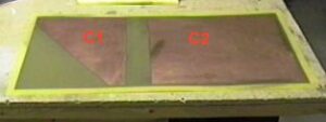 B is generally used (as it has 33% lower inductance) it has a nasty tendency to breakdown. The slightly thicker PCB holds-up much better and has proven to tolerate over-voltage well so far. Remember though that the increased inductance will slow the discharge and may affect performance, especially if a gas with an extremely short upper lasing level lifetime such as neon is used. The total board measures 30cm by 61cm (12″ by 24″). The capacitors are arranged as follows: First, etch a strip around the perimeter of the PCB 2 cm on the top side and 1.5cm on the bottom side. The reason for the difference is to avoid having both edges align. This helps reduce E fields at the edges which cause failures (It was found with the first laser that the PCB usually breaks down first at the edges where top and bottom copper areas stop and overlap – it is hoped that by not overlapping the edges the electric filed will be lower and hence the tendency to fail at that point). Next the cap is laid out as per the photo. The spark-gap side of the cap is etched as a right-angled triangle with one side (parallel to the tube) being 26cm (the length of the electrodes) and the other side 20cm. This shape is calculated to encourage a travelling-wave down the tube at the speed of light [6]. The distance from the gap to the tube is calculated according to (1-1/e)*L where e is the dielectric constant of the PCB used (roughly 4 for epoxy-glass board) and L is the 26 cm length of the tube electrode. A 2 cm gap is etched parallel to the tube axis to separate the two capacitor segments and the larger capacitor on the side opposite the spark gap consists of whatever is left – 26cm by 30 cm in length. The tube is mounted by soldering the thin brass electrodes (which protrude from the tube) to the copper-cladding of the PCB. The tube is soldered down the entire distance of the electrode being careful not to overheat the board which weakens it and causes the cladding to peel! Soldering time can be minimized by applying flux and pre-tinning the surfaces to be soldered with a thin layer of solder. The surfaces, both tinned, are then brought into contact and reheated to cause solder to flow and the junction to be made. After soldering the tube to the board the top of the PCB should be coated with urethane varnish to keep corona near the edges of the capacitor down (this occasionally leads to flashovers around the side of the PCB).
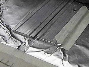
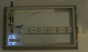
 A photo of the completed tube showing the channel which was machined into the plexiglas using a 3/4″ wide carbide router bit. Cap-head machine screws (6-32) are used to hold the halves together. The ends are capped by two pieces of plexiglas, also 3/8″ thick, sealed to the tube with silicone. Thin windows made from microscope slides cover the tube ends and a rear mirror will be added externally later (but are not required for operation).
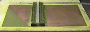
The laser as it will look assembled with the tube atop the capacitor. This one-piece design should yield optimally low inductance. The entire laser is 60 cm long by 30 cm wide.
Thin microscope cover slides are used as windows at each end of the tube. Look at the edge of the slide to determine the suitability for use with UV radiation: if the glass appears green it will not work – look for glass which appears clear white. Vacuum connections are made to two holes drilled into the end-caps. 1/8″ copper tubing is inserted into the holes and sealed with clear silicone.
 The spark gap is housed in a box made from three pieces of 3/8″ plexiglas with a 1/2″ hole drilled down the centre. Electrodes are two 10-32 brass bolts each of which has a rounded end (round surfaces allow the spark gap to have a lower self-inductance and a more predictable breakdown voltage). Each brass electrode is attached to the laser capacitors using strips of brass shim stock 25mm wide and soldered to the capacitors directly. The gap is open to ambient air via a small hole drilled into the assembly. This hole was made to allow the provision to purge the gap with pure nitrogen later if desired. A nitrogen purge of this spark gap is a good idea since air contains oxygen which quickly produces ozone – the sickly-sweet smell of ozone is quite prominent after the laser has been operated for a few minutes.
Visible here is the block of plexiglas (made from three pieces) in the centre of which resides the spark gap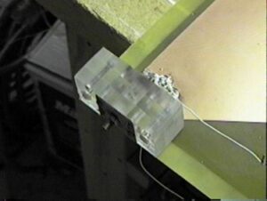 for the laser. Note the 3cm wide brass strips connecting this gap to the PC board below it.
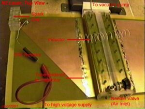
The vacuum system for prototype testing was an old Cenco single-stage pump, a Bourdon-type mechanical vacuum gauge, and a needle valve to regulate the tube pressure. This pump can achieve an ultimate vacuum of only 1 Torr however in the initial test setup little attention was paid to leaks so the ultimate vacuum is only about 10 Torr (still more than sufficient for this laser). In preliminary tests air was used as the lasant as pure nitrogen was not available at the time of the test. The needle valve was at one end of the tube (visible in photos of the laser as a silver valve at the front of the laser) and the pump/gauge at the other to allow air to flow through the laser. There were many vacuum leaks in the system which was hastily connected. This is unimportant since air is the lasant anyway however these leaks must be sealed properly if pure nitrogen or neon is used with this laser (especially if neon is used – it is not a cheap gas!).
At first the laser was powered with a simple power supply consisting of a 7300V, 5 mA transformer whose input was regulated with a variac and whose output was 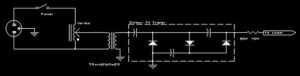 connected to the laser via a high-voltage diode (long-barrel TV type) and 50K Ohm resistor in series. This allows a maximum voltage of about 12kV across the laser which was enough to allow lasing however the laser was seen to laser asymmetrically: the beam appeared much brighter on the (parallel) side of the tube opposite the spark gap. Increasing the voltage by widening the spark gap and using a tripler between the transformer and the laser improved performance drastically! The original spark gap was set to about 5-6 mm. When the tripler was added that gap was widened to 8-10 mm. One must be careful not to exceed about 20kV as the capacitor PCB is 0.020″ thick (the dielectric itself as measured with digital calipers) and so can withstand about 20kV.
Results
The laser has been completed with preliminary tests run using ordinary air as the lasant. The laser ran successfully using air alone! Using pure nitrogen it was found that the unit produces about twice the output (estimated visually) as well as improves greatly in shot-to-shot stability. No rear mirror was installed for either of these tests although including one will certainly increase output power.
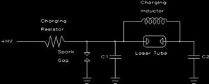
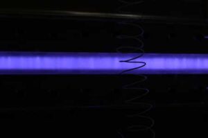
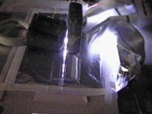
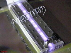 The laser tube is seen here firing. The coil of wire in the center of the photo is the charging inductor placed between the two capacitors.
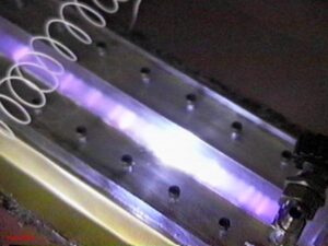 In this close-up view ‘hot spots’ can be seen in the discharge. It was found that these were reduced with the use of pure nitrogen gas but not entirely eliminated, esp. when the tube pressure was higher than optimal.
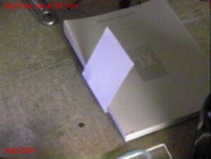
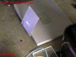
Identifying lasing was simple as seen in the photographs below. When the laser fires, a white business card places 30cm away from the front of the laser glows diffuse violet but no formed beam is seen. When the laser is operating, a very bright and well-formed beam is seen on the card (although the beam is actually UV, the paper used to manufacture business cards has fluorescent dyes in it to make it ‘whiter than white’. It is this fluorescence that is observed here). It was found that when very low voltages are used (about 10kV) the beam is asymmetric and much brighter on the side of the tube opposite the spark gap. As the operating voltage is increased the beam becomes more uniform across it’s width. Tube pressure was found to have a similar effect. When the tube pressure was too low (below about 15 torr) the output beam was also asymmetric. Optimal tube pressure (with air) was found to be about 60 torr. Increasing the pressure above about 100 torr caused the laser to stop lasing. It is interesting to note that each photo was a capture from a single frame of a video camera. The beam intensity is indeed quite high and a single laser pulse can be easily seen as a bright spot on the card.
 Here the laser is not actually lasing. The card glows with a diffuse violet light from both spontaneous emission from the laser as well as light from the spark gap. No formed beam is visible here.
 An Asymmetric output beam is seen here. The left side of the card is that opposite the spark gap.
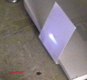 A proper beam produced when the capacitor voltage was increased to about 20kV and the tube pressure adjusted to about 60 torr. It still looks asymmetric, but better (and as good as it gets using plain air).
Although it works, using plain air as a lasant was found to result in several strange effects:
- Shot-to-shot operation was found to be erratic. When the charge-rate was set so that the spark gap fired about 2 Hz it was seen that only 50% of the time the gap fires was a laser beam present.
- At lower voltages and non-optimal pressures the beam profile was non linear and lasing was confined to the area around the electrode opposite the spark-gap side of the tube (see photo above)
- Power output was low and difficult to optimize – unusually high voltages were required (20kV plus) to make it lase reliably
When later tested using pure nitrogen – derived from liquid nitrogen by dipping a 2m long polyflow tube into a dewar of LN2 – these effects disappeared. BTW: liquid does not flow into the laser … during it’s 2m path through the tube the LN2 changes back into a gas long before entering the vacuum system. The gas source could just as easily have been from a tank with a regulator. Using pure nitrogen the laser was found to operate optimally at a pressure of 75 torr. Pulse repeatability was drastically improved when using pure N2 – every pulse resulted in lasing action! Power output was increased, and the beam profile was observed visibly to be consistent across – required when used as a pump for a dye laser. As well, parameters such as firing voltage and operating pressure were much more forgiving than when air was used. Any voltage between 10kV and 20kV was found to produce laser output and any pressure between 25 and 100 torr would work. For some time the laser was housed in a laboratory and supplied with nitrogen from a large tank. A regulator on the tank reduced the pressure to 20 psi. It was then sent through a needle valve and flows into one end of the laser housing. The other end of the laser housing was connected directly to a single-stage vacuum pump with a Bourdon (dial) vacuum gauge attached. The power source was the same as the prototype (a small sign transformer powered through a variac) with the secondary (7.3kV) boosted in voltage by an old colour TV tripler to a maximum of about 20kV. The output from the tripler passes through a 50K 10W wirewound resistor to regulate charge current before connecting to the top plates of the Blumlein laser capacitors. With pure nitrogen gas (flowing slowly) the pulse repeatability and power output are excellent and rival many commercial lasers. It is an excellent pump source for dye lasers.
 In this view of the laser discharge, shot from the top of the laser, a very consistent discharge is observed. Low-pressure nitrogen lasers of this type tend to be ‘forgiving’ in construction and have nice, consistent discharged which fill the entire lasing volume between electrodes giving a high laser gain. In higher-pressure lasers ‘hot spots’ resembling arcs between the electrodes are a major problem which may be solved through pre-ionization of the discharge volume or addition of helium to the gas mix (which serves to distribute the discharge more evenly – refer to Bastings [6]).
It may be noteworthy that during prototypical tests neon gas was tried in haste (540.1 nm green line). Neon did not lase, at the time thought to be likely due to the fact that there were many leaks in the crude vacuum system. The nitrogen laser line was seen the entire time (Indicating a major leak leaving enough nitrogen in the tube to lase). This is not surprising given that many TEA nitrogen lasers operate with a mixture of only 2% nitrogen and 98% helium! The presence of neon did, however, improve the stability of the air laser by acting as a buffer gas in the same role as that of helium in many commercial TEA lasers (Lasers such as the Lumonics Excimer lasers which can operate as nitrogen lasers with a suitable gas mix – see the TEA lasers page for details). During later tests the vacuum system was improved and a major leak around one of the end windows sealed. The laser is sealed well enough that it will still lase 24 hours after a pumpdown once sealed (i.e. the needle valves closed). Pure neon was tried again but failed to lase. This is likely because the upper lifetime of neon is only about 1.5 nS: an order of magnitude shorter than nitrogen. Combine the thicker 0.020″ PCB used (higher inductance, slower discharge) with this short lifetime and it can be understood why neon will not work in this laser. A laser designed for neon might be similar to TEA lasers which have sub-nanosecond discharge times (or even closer to a hydrogen laser which has similar lifetime dynamics to that of neon).
Possible Improvements
One major question is the asymmetric design of the laser where the capacitor on the ‘spark gap’ side is much smaller than the other. Assuming that the impedance of the spark gap is much higher than the transmission line (which it most likely is), each side of the laser should be equal in terms of size! Indeed, I can’t say that the geometry of this particular design has yielded any significant gains over the previous design which was symmetrical. Suffice it to say that to truly optimize the laser one must model it as a true transmission line and quite likely each capacitor would be similar in size.
Aside from a Blumlein, alternative designs [9] are possible in which energy from a primary, low-inductance capacitor is dumped across a discharge tube with a smaller capacitance across it. This design provides a lower driving impedance for the laser channel.
Another possible arrangement for a nitrogen laser is to use a Marx-bank generator to drive the laser tube. Such devices are capable of producing pulses of 100’s of thousands of volts with discharge times of one nanosecond or less! The basic Marx-bank consists of multiple high-voltage capacitors which are charged in parallel then discharged in series. I had constructed one years ago using ABS plastic plumbing for capacitors and plumbing TEE’s and carriage bolts for spark gaps. The entire apparatus could produce ultra-fast pulses of energy at about 150kV.
It is suggested that a simple laser could be built by putting a glass plasma tube [5] in the centre of such a Mark-bank making a simple coaxial arrangement with high-voltage capacitors surrounding the laser tube. This would be a compact arrangement and one which is almost optimal in terms of reduced inductance and hence fast discharge. Such an arrangement could easily pump nitrogen as well as other gases with even shorter upper-level lifetimes to lase.
References
[1] A simple pulsed nitrogen 3371A laser with a modified Blumlein excitation method
J.G. Small and R. Ashari
Review Of Scientific Instruments, Vol 43, Number 8, August, 1972, pp.1205
Describes a simple laser using acetate sheets as capacitors
[2] An Unusual kind of gas laser that puts out pulses in the ultraviolet
Scientific American, Amateur Scientist Column, June 1974
A simple nitrogen laser easily constructed by an amateur. Based on Small’s design in the above reference.
[3] Compact high-power TEA N2 laser B.S. Patel
Review Of Scientific Instruments, 49(9), Sept 1978
A compact TEA laser which required operates at atmospheric pressures and hence does not require a vacuum pump. Uses multi-segmented electrodes.
[4] Spark gap power switching circuit for … plasma gun Glenn Kuswa & Charles Stallings
Review Of Scientific Instruments, Vol 41, No 10, 1970, pp. 1429
Details construction of low inductance (7nH) spark gap switch which may be used for N2 lasers
[5]The poor man’s nitrogen laser David Phillips and John West
American Journal Of Physics, Vol 38, No. 5, May 1970
A small, simple N2 laser which does not use a Blumlein design but rather a capillary tube. Produces low powers which may not be suitable to pump a dye laser however the laser is easily constructed from parts available in the plumbing section of a hardware store.
[6] A simple, high power nitrogen laser
D. Basting, et al.
Opto-electronics, 4 (1972) 43-44
An optimized and compact high powered nitrogen laser which uses two flat-plate capacitors (top and bottom). Reported powers are 1.2MW for a 30cm tube. Also reported is the use of air instead of nitrogen gas.
[7] Travelling wave excitation of high power gas lasers
John Shipman, jr.
Applied Physics Letters, Vol. 10, No. 1, 1 Jan 1967
A long laser of Blumlein design. Includes data on using neon gas as a lasant.
[8]Fundamentals of Light Sources and Lasers
Mark Csele
ISBN 0-471-47660-9, John Wiley & Sons, 2004
A general reference covering UV lasers in chapter 10
[9]A Short High-Power TE Nitrogen Laser
Ernest E. Bergmann & N. Eberhardt
IEEE Journal of Quantum Electronics, August, 1973, pp.853
An alternative design to a Blumlein employing a discharge capacitance and a dumping capacitance.
Pulsed molecular nitrogen laser theory
Edward T. Gerry
Applied Physics Letters, Vol. 7, No. 1, 1965, pp. 6
Examines excitation mechanisms & saturation power output of N2 lasers
Along the lines of the Nitrogen laser is the Neon laser. When pure neon gas is used in a nitrogen laser a green line at 540.1 nm may be produced. The output power of this line is about 1/5 that of a nitrogen laser. There is one trick though: the discharge time must be ten times faster than the already fast nitrogen laser! I have attempted to lase this line in the above laser and it did not work: likely because my discharge was indeed too slow. Likely a laser built for neon would resemble a TEA laser (which does have a discharge time of about 1nS). Neon will lase on several other transitions as well. Details of this laser may be found in the following references:
The 5401A pulsed neon laser
Leonard
IEEE Journal of Quantum Electronics, March 1967, p.134
This is the best reference I’ve seen. It describes a neon laser which otherwise resembles a nitrogen laser
Observation of a super-radiant self-terminating green laser transition in neon
Leonard, et al
Applied Physics Letters, 15 Sept 1965, Vol 7, No. 6, p.175
Asymmetric visible super-radiant emission from a pulsed neon discharge
Clunie, et al
Physics Letters, 1 Jan 1965, Vol 14, No. 1, p.28
TEA Nitrogen (high pressure) Lasers
This laser, a variation of the low-pressure nitrogen laser described on this site, produces intense, short, pulses of UV radiation at 337.1nm. No vacuum pump is required as the laser operates at atmospheric pressures however the electrical discharge circuitry must be extremely fast in order for this laser to work.
Abstract
Presented is a simple TEA nitrogen laser which produces pulses of light using a Transverse Electrical discharge in gas at Atmospheric pressures. Since atmospheric pressures are used, no vacuum system is required making this an inexpensive laser to construct. TEA configurations are used for some nitrogen as well as some pulsed carbon-dioxide lasers. For a nitrogen TEA laser, it is possible to use ‘open air’ as the lasing gas since air is 78% nitrogen!
Although the idea of a TEA laser is tempting, since no vacuum pump required, construction this type of laser is by far more ‘touchy’ than the low-pressure design employing a vacuum pump. Ultra-fast discharges are required for the TEA laser (10 times faster than a ‘normal’ low-pressure nitrogen laser outlined on this page) which makes optimization of the transmission-line capacitors far more critical. Further, TEA lasers have a beam profile of only a few mm wide (usually 1.5 or 2mm) making it difficult to use as a dye laser pump source.
Introduction
A TEA nitrogen laser resembles a ‘traditional’, low-pressure N2 laser in having two long parallel electrodes with capacitors on either side and a spark gap however this laser operates without a vacuum pump (in some cases, such as a TEA CO2 laser, the laser discharge occurs at several atmospheres of pressure!). The gain of the laser is so high that in many cases the laser can use air as the lasing gas since air is 78% nitrogen anyway – the price is lower efficiency. As background reading be sure to view the low-pressure Nitrogen laser page on this site first since this laser shares many of the same design principles.
The first issue with the TEA nitrogen is the pulse width. The molecular nitrogen laser is self-terminating … upon discharge the nitrogen enters the upper lasing energy level then decays to a lower state emitting light at 337.1 nm in the UV. In a low-pressure N2 laser (e.g. the design outlined in Scientific American by James Small), about 20nS after the discharge begins the population of nitrogen molecules at the lower state exceeds that of the upper state and lasing terminates since population inversion, required for lasing, is no longer maintained. The lower level has a much longer lifetime than the upper level so lasing cannot be maintained continually like HeNe or other gas lasers.
In the case of nitrogen the problem is that the lifetime of the upper state, which really sets the width of the laser pulse in this case, is inversely dependent on pressure according to the formula [1]:
where t is the lifetime of the upper lasing level in nanoseconds and p is the pressure in the discharge tube in torr.
Hence in a ‘normal’ N2 laser operating at 30-60 torr the lifetime of the upper lasing level is about 20 nS. In a TEA laser the higher pressure reduces the lifetime of the upper energy state to about 2.5 nS. The pulse width of the TEA laser is hence reduced to about 1 nS. Now, construction of a ‘normal’ N2 laser is difficult enough given that particular attention must be paid to keep inductances very low. Consider the capacitors used – although tempting one cannot use regular 0.045″ thick PCB for an N2 laser since the self-inductance of the board is quite high which slows the discharge and hence it fails to work. In the TEA nitrogen laser the situation is ten times worse so that extreme measures must be taken to keep inductances low! Consider the characteristic impedance of a Blumlein transmission line given by [2]:
where Z is the impedance of the line in ohms, s the thickness of the dielectric and e the dielectric constant of the capacitor material, and L the width of the conductors in the transmission line.
The ultra-fast discharge required for a TEA laser dictates that we keep the dielectric as thin as possible which, of course, leads to problems with dielectric breakdown due to the high voltages required. Using the first formula we find that the lifetime of the ULL is 2.5ns so that logically our transmission line must discharge within that time. This dictates a maximum length for the transmission line based on the speed at which it discharges:
where c is the speed of light (3*108 m/s) and tp the length of the pulse. Since the later parameter must be kept to 2.5ns or less this dictates that the transmission line must not exceed 43cm where a dielectric with an e of 3 is used (Of course if polyethylene, mylar, or other materials are used for the caps this number will change accordingly). High dielectric materials will dictate a shorter width of the transmission line. Anything over this figure will result in energy being wasted since population inversion will end with the ULL lifetime.
Aside from keeping inductances low the second concern is distribution of the discharge. At low pressures, the discharge tends to smooth-out over the entire length of the electrode as required but at atmospheric pressures it tends to form a single spark or ‘hot spot’ at one point along the electrode. A fast-rising discharge waveform does help to a large extent however careful design if required to further reduce arcing. Several schemes exist to reduce this effect ranging from careful alignment of smooth electrodes via a micrometer [3] to a multi-segmented electrode using up to 27 small electrodes with 27 small capacitors instead of one electrode [4]. This is actually a reincarnation of a very old approach – one developed for the original N2 laser in the 1960’s. The original N2 laser (developed by Heard) employed an electrode composed of many segments. Pre-ionization may also be employed (see the bottom of this page). Commercially, many lasers use a pre-ionization technique in which a discharge through a small spark gap prior to the main discharge ionizes gas in the laser channel.
Finally, electrode spacing on a TEA laser is necessarily small in order to keep the E/p ratio (the ratio of electric field to pressure and discharge length, measured in V/cm-torr) to a target value. Research [7] shows that the E/p ratio of nitrogen is between 150 V/cm-torr to 300 V/cm-torr. The actual E/P depends upon the pulse length (actually, the product of pulse-length and pressure called the Ptp parameter) – the E/P rises as pulses become shorter so the expected E/P ratio for a TEA laser would be larger than that expected for a low-pressure design with a longer pulse length.
Assuming a value of 200 V/cm-torr (an “accepted” value), an applied voltage of 7500 volts, and a partial-pressure of nitrogen of 608 torr (80% of 760 torr), the electrode spacing would be only 0.6 mm! The same voltage, employed with an electrode spacing of 1cm, implies a pressure of around 40 torr (as employed in a low-pressure design, outlined on another page on this site). It might be added that the E/p ratio of air is higher than pure nitrogen – possibly as high as 385 V/cm-torr. A TEA nitrogen laser running on air would be expected to have a smaller electrode spacing than the same laser employing pure nitrogen while a ‘low pressure’ design employing air (and having fixed electrode spacing) would likely perform better at lower pressures than the same laser using pure nitrogen gas.
For wider electrode spacing, the E/P ratio could be modified by the addition of helium (an inert buffer gas). Commercial TEA lasers frequently use gas mixtures of only 2% to 5% nitrogen (with the balance helium) keeping the partial pressure of nitrogen low (so the E/P of the nitrogen component is matched) allowing the use of high pressure gas mixtures with wide electrode spacing (up to 5 cm) … see the description of such a laser at the bottom of this page.
A number of amateur laser constructors have described accounts of their TEA laser experiments. I have constructed two such lasers: the first a rigid ‘textbook’ approach and the second a ‘quick and dirty’ approach made with aluminum foil and plastic film which took only 30 minutes to construct. Bizarre as it may seem, the ‘quick and dirty’ laser outperformed the ‘better built’ one. If you are looking for a ‘scratch built’ laser project this laser is certainly the cheapest however don’t be surprised if it fails to lase on your first attempt as it is somewhat ‘touchy’ to align the components. Construction and materials also must be done carefully to eliminate stray inductances which will slow the discharge and cause problems. The ‘traditional’ nitrogen laser is considerably more forgiving. As well, if you are planning on pumping a dye laser consider that the beam width is quite narrow. It is possible, but trickier than with a low-pressure laser as a pump laser.
Prototype Design
The TEA laser resembles the low-pressure Nitrogen laser in design with the exception that the entire transmission line must be optimized for a much faster discharge. The figure below outlines the cross section of the laser which may be compared that of the low-pressure Nitrogen laser.
This ‘quick and dirty’ prototype laser, which worked well as seen in the photo below, was assembled in about 30 minutes from commonly available components. It is known that the electrodes need to be very smooth and parallel so I chose to cut these from a long piece of aluminum floor edging. This product is sold in Canada at Canadian Tire stores under the brand name ‘Shur-Trim’ (# 344P) made by Drummond Metal Products. It is a 25mm wide strip of aluminum with beveled edges – perfect for keeping the discharge elevated away from the capacitor underneath.
 Two electrodes, each 24cm long, were cut from the edging. The sharp corners which result were filed smooth and the entire edge was sanded with 600 grit emery cloth to ensure it was absolutely smooth.
The electrodes were held to the capacitor below it using two 5 lb. scuba weights. To adjust the gap two plastic alignment rods were used (you do NOT want to get too close to the charged capacitors as they will throw a painful arc).
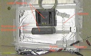 The capacitors were made from aluminum foil and polyethylene film. The poly film was 6 mil thick: it was left-over ‘Super-Six’ vapour-barrier (required by Ontario building codes) available from Home Depot. A piece of film about 40cm square was cut and the foil attached by masking tape. The bottom plate was 30cm wide by 45cm long and protruded from one side for connection to the spark gap. The top plates were each 30cm long by 9cm wide. Again these were simply taped to the plastic film. The foil was regular Reynolds aluminum foil. In terms of materials, I suspect regular foil is a better bet as it is more flexible and tends to bend easily when electrostatic force pulls it towards the plastic film (when high voltage is applied). Thicker foil, or even aluminum plates, might not be a benefit here as they will undoubtedly leave air gaps which lower capacity and increase inductance of the transmission line.
 The gap was made from workshop leftovers: a small steel “L” bracket and an 8-32 screw with round-ball nut (The kind used to hold lamp parts together). It was taped to the top of one capacitor. The other end of the gap was the aluminum foil which protruded from the bottom of the capacitor. It is important that the inductance of the gap itself be minimized in order to obtain the fastest possible discharge – as such sharp edges must be avoided like they are here.
The spark gap was set to about 3mm. It is important that it be set reasonably small since this gap sets the voltage at which the laser fires. If the gap is set too wide the voltage will exceed the breakdown of the rather thin dielectric and the laser will quickly fail.
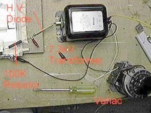 The power supply for this laser is a very simple one consisting of a 7.3kV/5mA transformer from an old Xerox copier, a variac to regulate the AC input, a high-voltage diode from an old TV, and a 100K, 13W wirewound charging resistor.
Results
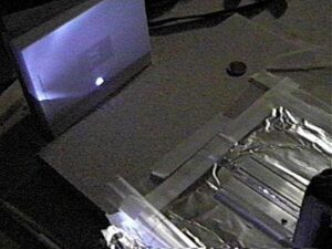 The laser is seen operating here. It was observed to operate, with the spark gap set small enough, at a minimum voltage of about 5kV but operated much better when the gap was widened slightly and the firing voltage set to about 6kV. The gap between the parallel electrodes was set to 1.2mm on the front, 1.1mm on the rear. It is interesting to note that the laser would NOT work if the gap was too narrow … at least 1mm of gap was required to allow it to lase.
Asymmetric output was found between emission from the rear of the laser and the front. The front output was estimated visually to be about 4 times more powerful. No mirror was used but a single mirror at the rear of the laser will certainly improve the output.
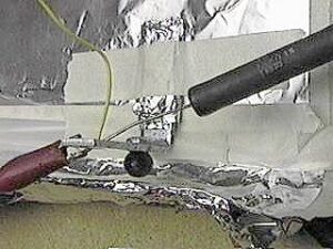
 The operating laser as seen from the top. The gap between the two electrodes must be carefully adjusted so that the discharge occurs along the entire length of the gap, not just at one point. This is quite critical and requires a bit of ‘fiddling’ to get it to work. At first, a single spark appears atone end. Open that end very gently until the spark begins to move towards the other end of the laser, distributing itself evenly along the distance. A bright blue spot should then occur on white paper placed in front of the laser (fluorescence from the paper itself: the actual output of this laser is UV and as such, is invisible).
The spark gap, btw, should be shielded as it is quite noisy and produces intense light. In the photo above a rag was used to shield it temporarily to avoid having the video camera lose focus.
Improved Design
The first problem encountered was longevity of the capacitor dielectric. A single sheet of 6 mil polyethylene lasted only about 100 shots before breakdown occurred. Two sheets of this material were tried as well. While this improved lifetime (it never did fail) it also decreased output quite drastically. This is due to the decrease in capacitance (and hence energy storage) as well as increased self-inductance of the capacitors. So far, the best performance has been obtained by using drafting mylar (polyester) film. A single 2.5 mil thick sheet has been used quite successfully at a low firing voltage of 5kV. The tradeoff to use a low voltage was made in order to allow the thinnest dielectric possible. By trial and error it has been found that the best performance has been obtained using this thinner dielectric (and hence lower voltage). It has also been determined that the optimal capacitor width is about 9cm on the side nearest the spark gap, and wider at 15cm on the opposite side. Increasing capacitance of the side opposite the gap produced a notable increase in output power but increasing the ‘gap’ side did little to affect the output. The gap was located near the rear of the capacitor.
A second laser has been constructed using the design principles above. It was built into a 17″ by 10″ by 2″ aluminum chassis box. The box accommodates capacitors of 9cm and 15cm width and will features decent mechanical compression via multiple plastic screws to hold the electrodes firmly to the capacitor plates. Electrodes of length 24cm and 36cm can be accommodated. Longer electrodes improve output. As well there is provision for a rear mirror via a three-screw mount as part of the case. The small 5kV supply will be built right into this box to keep it compact and safe.
If attempting to build a TEA laser like this, use thin dielectric but one thick enough to prevent breakdown (this must be determined experimentally). As well, electrodes must be kept exceptionally flat to ensure it operates … the chassis in the design seen here was bolted to a 3/4″ piece of particle board to keep everything flat – the prototype was built directly onto a piece of flat board. Use a voltage of around 5kV and remember that alignment of the electrode gap is critical!
The 5.0kV 200uA power supply was scavenged from an old laser printer and is tucked into the upper-left corner of the chassis. Taken from an old HP Laserjet, the module uses a 24 VDC supply (at 0.15A) and produces 5kV originally used for charging the drum. The spark gap is built from two pieces of plexiglas with a brass terminal which attaches to one capacitor. The gap was set to about 3mm (until it fired about twice per second) and the electrode gap adjusted for maximum output. The optimal gap was found to be 1.5 mm at the front and 1.4mm at the rear. Again, gap adjustment was crucial for proper operation. When properly adjusted any ‘hot spots’ were spread down the entire length of the electrodes as much as possible (although the photograph at the top of this page still reveals shows several ‘hot spots’). For the most part, a nice dull purple glow was evident down the entire length of the electrodes. The electrodes are held down to the aluminum foil by many plastic screws.
Download a short movie showing the laser operating TEA LASER FIRING (633K file size). As the movie plays you’ll hear it firing many times but will only see the spark gap and output (on a white business card) flash periodically. This is because the fast pulse may be missed on many frames as the camera records.
Improvements and Updates
Like the low-pressure laser on this site, one may argue that the laser should have been designed in a symmetrical manner with both capacitors of equal size. Assuming that the impedance of the spark gap is much higher than the transmission line (which it most certainly is for a laser such as this), each side of the laser should be equal in terms of size! This concept seems to be reinforced by some researchers [6] (e.g., Compact High-Power N2 Laser: Circuit Theory and Design, Schwab et al, IEEE Journal of Quantum Electronics QE-12, No. 3, March 1966, p.183) where the author essentially states that “Considering rise times of about 25ns, which are inherent to many reported N2 lasers, the traveling-wave concept becomes obsolete.”. Of course this research was referring to a low-pressure design in which timing is far less critical but it does outline a potential flaw in ‘over-optimizing’ the design to include a triangular, smaller, capacitor on the sparkgap side of the laser.
Alternative Electrode Options
The single biggest problem with the approach of using two single, long electrodes at atmospheric pressures are ‘hot spots’ which resemble an arc in the discharge. Critical alignment may reduce these effects but not eliminate them. Three approaches to fix this problem are (i) preionization of the gas between the laser channel, (ii) addition of helium in the discharge, and (iii) the use of multi-segmented electrodes. The first approach is used in commercial excimer lasers (see below) in which multiple spark gaps fire before the main discharge occurs. UV light emitted from the sparks preionizes gas in the laser channel. The second approach, of adding helium, is also employed in excimer lasers when using nitrogen gas. Lumonics excimer lasers, for example, utilize a mixture of only 2% nitrogen and 98% helium. This is mentioned in the article by Bastings, et al, [2]. The third approach, using multi-segment electrodes, is described by Patel [1] in which the author uses an electrode with 5 segments. The impedance of his capacitors is stated as 0.0527 ohms/m. The dielectric is two sheets of 0.125mm thick material. Reported output power is 1.0 MW with 0.6 nS pulse widths. An article by Herden [4] presents a similar design utilizing 25 electrode segments i a 27cm long laser. Capacitors and electrodes were fabricated from self-adhesive copper strips and mylar foil 0.2 mm thick. Power outputs of 400kW with a FWHM of 0.3ns are reported using open air as the lasing gas.
Dye Laser Pumping
This laser is approaching the level where it can be used as a pump source for a dye laser. The main problem here is one with optics: the thin pump beam is difficult to focus onto a dye cell. Given the wide dispersion of the beam though it may not be as tough as once assumed. At a distance of 46cm from the front of the laser the beam is observed to have a width of 4mm. A lens from an HP Laserjet was used to focus this beam to a thin line which appears to be suitable for pumping a dye. The next step is to build a suitable dye laser with a small cell. This design will be based on my original design detailed on another page on this site.
A Commercial TEA Laser
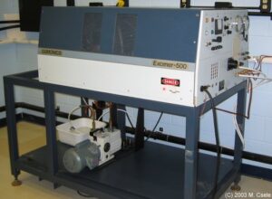
While TEA nitrogen lasers are available commercially one of the easiest lasers to convert to a nitrogen TEA is an excimer laser. In the Niagara College laser lab I had done this with a Lumonics Excimer-500 which runs from a mix of nitrogen and helium gases. Real excimers require a halogen gas (fluorine or chlorine) which is toxic and expensive – in our lab we allowed students to mix their own gases using nitrogen and helium which is much safer and cheaper while giving the same experience as mixing a real excimer (i.e. nitrogen, like the halogen in an excimer laser, is used in small quantities and introduced using a ‘boost bottle’ arrangement). This particular laser is a class-IV laser (given that the output of 400mW is in the UV region) and was used both for gas-mixing experiments and to pump dye lasers (see the dye laser page on this site).
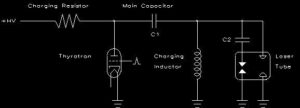
The Lumonics Excimer-500 laser, like most commercial excimers, uses a single large capacitor (C1) which is discharged through a transverse electrode via a hydrogen thyratron. The laser features multiple preionizing sparks along the transverse electrodes shown as the gaps with capacitors C2. UV light from the sparks ionize gas in the laser channel which conducts current from capacitor C1.
The normal mixture for this laser is 2% nitrogen and 98% helium with an operating pressure of 30psig. Lasing the N2+ ionized molecular species at 428nm can also be accomplished by lowering the concentration of the nitrogen to 0.2%. It was found, experimentally, that pulse-to-pulse consistency (required for dye laser pumping) was improved greatly by lowering the operating pressure of the laser to 17-20 psia (where 15psia is atmosphere).
A few key references for TEA lasers:
[1] Compact high-power TEA N2 laser B.S. Patel
Review Of Scientific Instruments, 49(9), Sept 1978
A compact TEA laser which required operates at atmospheric pressures and hence does not require a vacuum pump. Uses multi-segmented electrodes.
[2] A simple, high power nitrogen laser
D. Basting, et al.
Opto-electronics, 4 (1972) 43-44
An optimized and compact high powered nitrogen laser (low-pressure) which uses two flat-plate capacitors (top and bottom). Reported powers are 1.2MW for a 30cm tube. Also reported is the use of air instead of nitrogen gas. Not a TEA laser but a good analysis of design principles provided
[3] Compact TEA N2 Laser E.Bergmann
Review Of Scientific Instruments, 48(5), May 1977, pp. 545
A simple TEA laser using two aluminum electrodes and 0.4mm epoxy-glass PCB for the capacitors. Includes a mechanism for keeping the electrodes aligned.
[4] Compact high power subnanosecond nitrogen and ‘open air’ lasers at 760 torr W. Herden
Physics Letters, Vol. 54A, No. 1, 11 August 1975
A multi-segmented Blumlein laser which works with open air as a laser gas.
[6] Spark gap power switching circuit for … plasma gun Glenn Kuswa & Charles Stallings
Review Of Scientific Instruments, Vol 41, No 10, 1970, pp. 1429
Details construction of low inductance (7nH) spark gap switch which may be used for N2 lasers
[7] Compact High-Power N2 Laser: Circuit Theory and Design Adolph Schwab & Fritz Hollinger
IEEE Journal of Quantum Electronics, QE-12, No. 3, March 1966, p.183
An excellent analysis of transmission circuit theory as applied to a low-pressure nitrogen laser (equally applicable, though, to a TEA design).
[8] Pulsed molecular nitrogen laser theory Edward T. Gerry
Applied Physics Letters, Vol. 7, No. 1, 1965, pp. 6
Examines excitation mechanisms & saturation power output of N2 lasers
[9] Investigation of the Paschen curve of nitrogen … D.W. Scholfield, et al
Journal of Applied Physics, Vol. 76, No. 3, 1994, pp. 1469
The Paschen curve for nitrogen, and other gas parameters, are investigated from 0.336 to 685 torr.
Laser-Pumped Dye Lasers
Abstract
This simple add-on to enhance the usefulness of the nitrogen laser is a dye laser. Simple to construct, the only problem is obtaining the exotic organic dyes used (not really a huge problem though: there are a few suppliers around).
The Basics
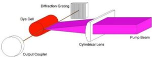
This laser works by focusing the UV beam from a nitrogen (or excimer) laser to a thin line on the surface of a cell containing a dye solution using a cylindrical lens. The dye is excited along a line on the inside surface of the cell, the excited ‘shaft’ of dye molecules forming the gain medium from which a beam emerges from the ends of the dye cell. The dye cell itself is made of quartz glass to pass the 337.1nm radiation without attenuation (although regular glass will work with reduced efficiency). The cell is typically 5mm dia. inside and only 1 cm in length.
Depending on the dyes used, mirrors may be omitted (at least for initial testing). With a small (100 kW) nitrogen laser of the type described elsewhere on this site, I was able to make a solution of the common dye 7-diethylamino-4-methylcoumarin lase super-radiantly! This dye is used in fabric detergent as a whitening agent. You must use a pure solution of the dye in methyl or ethyl alcohol for this laser. The dye itself may be obtained from a large lab chemical supply house such as Sargent-Welch Scientific or from a source such as Lambda-Physik or Exciton. The dyes are not overly expensive as only a small amount (much less than 1 gram) is required for a solution with one litre of alcohol. I normally use methanol as it is cheap and readily available in very pure (> 99.99% pure) form – most chemical supply houses carry methanol in pure form (in my case ‘cleanroom grade’).
The dyes used in these lasers are highly toxic and so must be handled with proper precautions. Some interesting dyes I have experimented with are:
- 7-diethylamino-4-methylcoumarin: A very easy to lase dye (high gain) producing laser output in the blue and green portion of the spectrum.
- Rhodamine 6-G: Another high-gain dye which produces laser beams tunable in the green-yellow to red portion of the spectrum. Experiments show this dye, in a methanol solution, is the most powerful dye in a nitrogen-laser-pumped laser.
- Sodium Fluorescein: A lower-gain dye producing light in the green to yellow region. Easy to obtain since it is used extensively in biology labs.
- 4-methyl Umbelliferone: A weak dye producing light from deep blue through violet and into the near-UV portions of the spectrum.
Details Of My Prototype N2-Laser Pumped Dye Laser …
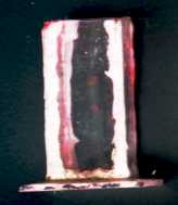 My very first dye laser was a proof-of-concept, hurriedly built and quite precarious-looking for a laser. Built on a piece of 2-by-4 lumber, the entire laser itself was only 15 cm long. The dye cell, shown to the left, consisted of five pieces of cut microscope slides held together with silicone. The cell was 1cm square by about 2.5cm tall. It was simply filled with an appropriate dye solution and placed on the base of the laser. Light from the nitrogen pump laser (also described on this site) was focused to a ‘line’ on this cell using an inexpensive glass cylindrical lens. The lens itself was made of quite cheap glass and likely absorbed a good deal of the UV pump light as well – the laser still worked despite this though, the spoils of having a very large pump laser!
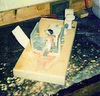 This first dye laser consisted simply of a dye cell with two flat mirrors on either side acting as a cavity – all components were mounted on a 2-by-4 wood base. Optics for this first laser consisted of an front-surface aluminum mirror and a 70% reflecting / 30% transmitting beamsplitter mirror for the output coupler. Each mirror was placed in a 3-point mount which allowed adjustment. Adjustment was surprisingly easy though since the dye first used (7-diethylamino-4-methylcoumarin) will lase superradiantly! The dye was made to lase first by adjusting the focus of the pump beam. Mirrors were then aligned until the output beam appeared much brighter. The pump beam may then be defocused to cease superradiant operation (i.e. laser normally with mirrors). Lasing is verified by blocking the path to the rear mirror alone which stops the output beam.
My First Research Laser
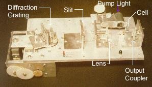 My first research laser (built for a science-fair project and constructed in 1983) consisted of a 1cm long quartz glass tube filled with solutions of organic dyes such as 7-diethylamino-4-methycoumarin and rhodamine-6G. UV light from the nitrogen laser is focused onto the dye to excite it and stimulate laser action. A cylindrical lens mounted on an old microscope focusing attachment allows the UV light to be focused to a fine line on the dye surface (which is required for lasing action).
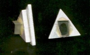 The mirrors were the same inexpensive ones used in my first prototype dye laser. The rear mirror was cut from an aluminum, first-surface mirror made for use in telescopes with a reflectivity of 85% (these are easily obtained and quite flat!) and the O.C. a 70%R/30%T beamsplitter (which I cut myself from a larger piece as evident from the crude fracture visible in the photo).
With a 1cm long amplifier, the threshold gain of the laser is over 26m-1: the dye amplifier must hence have a small-signal gain of at least this value (and probably a lot higher – dyes can have small-signal gains of up to 500m-1).
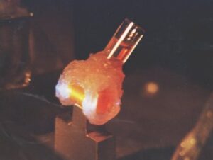 The dye cell itself was a 1cm long piece of quartz tubing into the side of which I filed a hole to admit the dye. I attached a standoff of glass tubing using clear silicone to permit filling of the cell. Here UV light at 337.1 nm wavelength from the nitrogen laser is focused by a plane-convex lens to a line on a 1cm dye cell made of 7mm quartz glass. The intensely excited dye molecules at the focus of the UV ‘pump’ light lase readily – When the pump beam was focused sharply on the dye cell it lased superradiantly (with no external mirrors!). Clearly visible here is the dye cell in operation. To the left the output coupler is visible. The bluish light on either side of the excited dye is the pump beam hitting the clear silicone used to seal the cell.
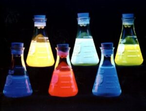 The dyes used in my experiments. They are lit via a UV lamp from above and hence are fluorescing brightly in this photo. The strongest dyes used were Rhodamine-6G and 7-diethylamino-4-methylcoumarin. Other dyes used included Sodium Fluorescein and 4-methyl Umbelliferone. All dyes are dissolved in either methanol or ethanol.
The dyes used were laboratory grade and not as pure as those normally used for dye lasers. These are considerably cheaper, however, no doubt there was a price to pay in terms of efficiency of the laser – still, given the enormous gain of the laser these inexpensive dyes worked well.
The New Dye Laser (2004)
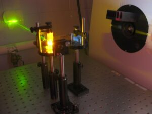
In 2004 a group of photonics students built a dye laser for our laser lab. This laser employed a quartz fluorimeter cell (with four clear optical sides) of 10mm * 10mm dimensions and was pumped by a Lumonics-500 excimer laser running a mix of 2% N2 and 98% He at a pressure of 5 psig. Pump light from the Lumonics (UV) is not visible here except for some fluorescence as it passes through the cylindrical lens and bright fluorescence at the cell. An aluminum HR is visible in this photo (with two protruding adjustment screws) and a 50% reflecting beamsplitter for an OC. Rhodamine-6G in a 1*10-3 Molar solution of methyl alcohol is seen here operating in the yellow-green with the beam made visible by fog. The solution is made by dissolving 0.0457g of Rhodamine-6G into 100ml of methanol (The molecular weight of Rhodamine is 457g so that 0.457g per liter of alcohol is required) as measured using a precision microbalance scale.
Fluorimeter cells are expensive at $250 each however the quality of the cell is much higher than homebuilt cells and corners of the cell are almost perfectly square (unlike many cheaper cells in which the corners are rounded). Being made of quartz, of course, helps since it is quite transparent to UV radiation. The cylindrical lens in this case is an inexpensive one made from BK-7 glass. BK-7 has a transmission of over 90% at 337.1 nm making it an economical choice for focusing pump power onto the dye cell – quartz would be the best choice but it was difficult to locate a quartz cylindrical lens.
All opto-mechanical components here are standard including mirror mounts with angular adjustment screws, a universal prism mount used to hold the dye cell, and a lens mount for the cylindrical lens. The mounting post for the cylindrical lens is attached to a base with slots allowing the entire lens to be moved closer or further from the dye cell. When ‘tightly’ focused the cell lases superradiantly and hence is not tunable. Normally the laser is made superradiant, optics aligned carefully, then the pump lens is ‘backed-off’ until the laser is no longer superradiant. To prove the laser is operating normally the optical path between the cell and each optic is blocked at which point lasing ceases.
 The laser is seen here with a diffraction grating in place of the HR making it tunable. In this animated GIF the laser is seen operating at two wavelengths, orange and yellow-green, as seen on the wall where the output beam strikes.
References
Dye laser stimulation with a pulsed N2 laser line at 3371A J.A. Myer, et al. Applied Physics Letters, Vol 16, Number 1, 1 January 1970, pp. 3 Describes the use of a pulsed-N2 laser to drive a dye laser along with cylindrical lens to focus the UV light to a line on the dye cell.
Tuned nitrogen laser pumped dye laser G. Capelle and D. Phillips Applied Optics, Vol. 9, No. 12, Dec. 1970 An excellent article which discussed tuning a dye laser using a grating as well as dye cell design.
Repetitively pulsed tunable dye laser for high resolution spectroscopy T. W. Hansch Applied Optics, Vol. 11, No. 4, April 1972 Describes the finer points of tuning a dye laser using both a grating and an intra-cavity etalon.
Neutral Neon Lasers
Unlike the ‘normal’ helium-neon laser with outputs in the red (633nm), orange (612nm), and green (543.5nm), a pure neon laser delivers pulsed output on different wavelengths. Neon features various sets of energy levels and the laser described here uses adifferent set of energy levels than those normally used for a helium-neon laser.
Abstract
A helium-neon laser tube is modified for use with pure neon gas in order to lase a number of neutral-neon superradiant transitions. A pulsed laser, energy is supplied in the form of a fast discharge from several low-inductance ceramic capacitors. Although the green transition at 540.1nm was expected, an orange transition at 614.3nm was dominant. Highly asymmetric output was seen with laser output observed only from the ‘live’ end of the plasma tube. Optimal output was observed at a neon pressure of 0.12 torr.
Background
It is well known that low pressure nitrogen gas excited by a massive electrical current in a traveling wave discharge [1][2] produces superradiant emission at 337.1nm. Neutral neon gas has a similar self-terminating transition at several wavelengths including 540.1nm in the green which can be excited in a similar manner [3][4]. Nitrogen can also be excited in a longitudinal tube arrangement [5] in which small-diameter plasma tubes are excited with a fast electrical discharge producing over 1kW.
Neutral neon has several high-gain transitions [6] at 540.1nm, 594.5nm, and 614.3nm when a long, thin capillary filled with the gas is driven by a high-voltage discharge with pulses of 30kV. Low pressures (0.3 torr) favour the orange and yellow transitions while higher pressures (3 torr) favour the green transition. Other researchers [7][8][9][17] describe similar success in lasing these transitions
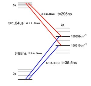 Consider the Helium-Neon laser for which the energy level diagram is seen to the left. In this laser neon is elevated to the upper-lasing level (denoted 1s22s22p55s1) via pumping from energetic helium atoms. From the upper levels (a cluster of four of them) neon decays to one of ten lower levels (denoted 1s22s22p53p1) producing one of the transitions shown here in red. The lower levels have shorter lifetimes than the upper levels so population inversion is ensured. Lower levels depopulate to a metastable state by spontaneous emissions of approximately 600nm (the blue transitions) and finally collision with tube walls returns neon atoms to the ground state.
The neon laser described here operates on transitions between the lower-lasing levels of the helium-neon laser and the metastable state in the system (i.e. the blue transitions shown). In the helium-neon system these transitions serve to rapidly depopulate the lower-lasing levels however here they become the upper-lasing levels. The energy-level system, as described, is not conducive to CW laser action since the lifetime of the upper-lasing levels is much shorter than that of the metastable state which serves as the lower-lasing level [14]. In this case, like that of the nitrogen laser, the mechanism of the laser must pump the upper-level quickly to ensure an inversion exists. Shortly thereafter, laser action may ensue but the transition will be self terminating and lasing action will cease.
Without helium in the system electron collisions are necessary to pump neon atoms directly to the upper-lasing levels. The presence of helium would hinder, not help, laser action since it would pump the incorrect energy levels in neon for the desired transitions.
Each set of levels (shown as ‘3p’ and ‘3s’ in the diagram) consist of clusters of multiple individual levels. In Paschen notation these are labelled consecutively as ‘2p’ and ‘1s’ respectively. When in the 2p (Paschen) level, the angular momentum and spin of the neon atom (with five valence electrons still in the core) combine to form ten allowed energy levels denoted 2p1 through 2p10. These ‘2p’ levels are the same as those which serve as the lower-lasing levels (LLLs) of the ‘normal’ HeNe CW transitions: the 2p1 level serving as the LLL for the 730nm IR transition, the 2p4 level for the 632.8nm red transition, and the 2p6 level for the 612nm orange transition. In this particular experiment, the transitions of interest here are the 2p1 to 1s4 transition at 540.1nm, the 2p4 to 1s5 transition at 594.4nm, and the 2p6 to 1s5 transition at 614.3nm.
Neon Transitions from NIST (ref 11) While numerous transitions would apparently be possible (fourty, in all), not all are probable since quantum mechanics selection rules dictate that certain changes in J (the L-S coupling term) are necessary for ‘allowed’ transitions [10]. In the case of the 540.1nm transition the actual transition is from a level designated 2p5(2P1/2)3p (with J=0) to a level designated 2p5(2P3/2)3s (with J=1) [11]. The change ΔJ = 1 is an allowed change. Similarly, the 614.3nm transition results from a transition between a state with J=2 to another state with J=2 – again, an allowed change. These levels are outlined to the left in an excerpt from [11] outlining the energy levels and J terms for each.
Experimental Setup
In one of the original reports of superradiant transitions [8], Heard mentions that two dielectric mirrors with peak reflectivity at 632.8nm were used in a plasma tube 40cm long and 1mm in diameter. Examining the use of a helium-neon laser tube for repumping experiments [12], which features a port allowing attachment to a turbomolecular pumping system, it is evident that such a tube should serve well to lase these transitions.
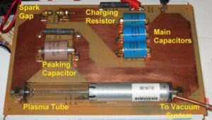 Figure 1: Experimental Setup
The entire laser was constructed on a piece of single-sided FR4 printed-circuit board approximately 30cm by 20cm in size as pictured in figure 1. Capacitors are mounted to the board via copper straps soldered to the board and the plasma tube itself is mounted on the board via two fuse clips. The spark gap consists of two solid brass ornamental nuts with smooth, rounded, ends approximately 5mm apart. Traces on the board are designed to be as wide as possible and the layout minimizes inductance of the discharge path. Three 460pF/30kV ‘doorknob’ capacitors in parallel are charged from a small neon sign transformer controlled with a variac via a voltage tripler through a 50K 10W wirewound resistor. When the capacitors charge to a suitable voltage the spark gap discharges through a peaking capacitor (with a function described in [5]) and through the plasma tube producing a fast discharge.
A Melles-Griot 05-LHR-099 laser tube was used in this experiment – this tube has the OC mounted on the anode end of the tube and is designed for CW red (632.8nm) emission. Optically, HeNe tube mirrors are peaked for reflection in the red however both mirrors have an estimated transmissivity of >50% at 540nm and >30% at 600nm. In this respect they should not impede the output of superradiant emission at any of the lines described and may, in fact, help improve the quality of the output beam.
It is hypothesized that the laser can be made to operate optimally in the green at 540.1nm and quite possibly in the orange at 614.3nm.
Results
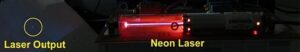
With the system configured as above the tube was evacuated to a pressure of better than 10-6 torr using a turbomolecular pump [13]. The tube was then filled with research grade neon to a pressure of 10 torr and the pressure gradually reduced as the laser was operated. Orange superradiant output was observed at pressures between 1.6 torr and 0.05 torr but the optimal pressure was found to be 0.116 torr. Various peaking capacitors were tried including no capacitor, 25pF, and 100pF. Weak output was observed with no peaking capacitor as well as when a 100pF capacitor was installed however optimal output occurred with the 25pF capacitor installed as per figure 2.
Output was observed from the ‘hot’ end of the tube only and never from the grounded end as per reference [6] (this is the OC end on the original tube in which the OC was located at the anode). At various pressures the output was analyzed with a grating spectroscope and found to be entirely monochromatic consisting of the 614.3nm line only – the expected green output at 540.1nm was never observed in this configuration.
Pure neon gas produced the best results and dilution with gases such as argon or helium decreased the power output until lasing ceased. With 25% of helium in the mixture the laser was found to cease operating entirely. Incidentally, with a helium-neon mixture the red line at 632.8nm was never observed.
At the low pressures involved the discharge in the plasma tube appears violet as opposed to the characteristic orange neon colour. It was also observed that repeated usage of the tube in this manner destroyed the OC optic, with the delicate dielectric coating visibly damaged. While this has apparently not impaired 614.3nm output, the tube is now incapable of oscillating at 632nm when filled with an appropriate helium-neon gas mixture.
Conclusions
Reliable output at 614.3nm was observed however the expected output on the green line was not observed. No attempt was made to measure the discharge current nor the time frame of the excitation pulse. The experiment (as well as others in the literature) seem to suggest that a faster discharge is required in order to favour the green 540.1nm transition – many successful experiments utilize segmented electrodes with very small capacitances for an extremely fast discharge which appears to be required.
A subsequent search of available literature [15][16] details that the 614.3nm line is favoured by shorter (30cm long, 3mm diameter bore) tubes operated at low pressures (approx. 1 torr), while the 540.1 nm line is favoured in longer tubes (100cm long, 3mm diameter bore) tubes operated at higher pressures (approx. 7 torr). With longer tubes, a pulse transformer or Marx-bank generator is required to supply the extraordinarily high voltages required (up to 200kV).
References:
[1] An Unusual kind of gas laser that puts out pulses in the ultraviolet
Scientific American, Amateur Scientist Column, June 1974
A simple nitrogen laser easily constructed by an amateur. Based on James Small’s design in Review Of Scientific Instruments.
[2] Travelling wave excitation of high power gas lasers John Shipman, jr.
Applied Physics Letters, Vol. 10, No. 1, 1 Jan 1967
A long laser of Blumlein design. Includes data on using neon gas as a lasant.
[3] The 5401A pulsed neon laser Leonard
IEEE Journal of Quantum Electronics, March 1967, p.134
The use of neon in a crossed-field laser with multiple electrodes
[4] Observation of a super-radiant self-terminating green laser transition in neon Leonard, et al
Applied Physics Letters, 15 Sept 1965, Vol 7, No. 6, p.175
[5] The poor man’s nitrogen laser David Phillips and John West
American Journal Of Physics, Vol 38, No. 5, May 1970
A small, simple N2 laser which does not use a Blumlein design but rather a capillary tube.
[6] Asymmetric visible super-radiant emission from a pulsed neon discharge D.M. Clunie et al
Physics Letters, Vol 14 No 1, Jan 1965
Output at 594.4nm and 614.3nm observed on 2P4-1S5 and 2P6-1S5 transitions
[7] Superradiant transitions in argon, krypton, and xenon K.G. Erics, et al
IEEE Journal of Quantum Electronics, 1967, pp. 94
[8] Super-Radiant Yellow And Orange Laser Transitions in Pure Neon, H.G. Heard
Proceedings Of The IEEE, Oct. 1964, pp. 1258
Using a 40cm tube of 1mm bore filled with 0.2torr or Neon laser action is observed at 611.8nm and 594.0nm. Performance improves when dielectric mirrors centered at 632.8nm are included
[9] Laser-Ubergange und Superstrahlung bei 6143A und 5944A in einer Gepulsten Neon-Entladung, D. Rosenberger
Physics Letters, Vol 13 No 3, Dec 1964
Output at 594.4nm and 614.3nm observed in a tube 20cm long by 1mm dia. filled with 0.4 torr of pure neon. Entire article is in German.
[10] Section 3.12 in Fundamentals of Light Sources and Lasers (ISBN 0-471-47660-9), John Wiley & Sons, 2004
[11] Handbook of Basic Atomic Spectroscopic Data Jean E. Sansonetti and W. C. Martin
NIST eBook
[12] Helium-Neon Lasers Page including repumping experiments.
[13] He-Ne reprocessing lab describing the vacuum system.
[14] Section 5.3 in Fundamentals of Light Sources and Lasers (ISBN 0-471-47660-9), John Wiley & Sons, 2004
[15] Shape and duration of superradiance pulses corresponding to neon lines, A.A. Isaev, et al
Soviet Journal of Quantum Electronics, Vol 2 No 1, July-Aug 1972
[16] High-power nitrogen and neon pulsed gas lasers, I.I. Magda, et al
Soviet Journal of Quantum Electronics, Vol 3 No 3, Nov-Dec 1973
[17] Pulsed Neon Laser with 350-psec Pulse Duration and Subnanosecond Jitter at 6143A, T.J. Davies and M.A. Nelson
Applied Optics, Vol 12, No 4, April 1973
Repumping Helium-Neon Laser Tubes
Abstract
Presented is an outline of the process required to pump-down and fill the gases in a helium-neon laser tube. Although a completely ‘from scratch’ tube could be done in the same manner, a commercial tube is employed here as this process was originally developed for a student lab in a high-vacuum and thin-film technology course (PHTN1432) that I taught for almost 20 years.
Background: HeNe Energy Levels
The helium-neon was the first visible CW gas laser discovered. An electrical discharge in mixture of helium and neon gases at low pressures transfers energy by electron collisions to the more abundant helium atoms exciting it to a level 20.61eV above ground. Excited helium then collides with the larger neon atoms elevating them to a level 20.66eV above ground. From there, the neon atom falls to a lower level emitting a red photon of light (632.8nm) then makes it’s way to ground state again.
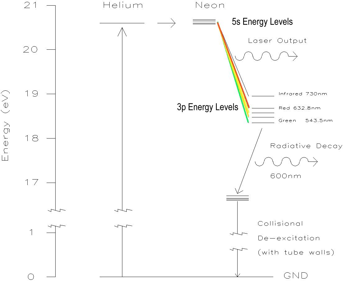
The helium-neon (HeNe) laser contains helium and neon gases at a ratio of about 10:1. Helium serves as a ‘pump’ gas allowing energy to be coupled into neon atoms at the desired energy level. In order for lasing action to occur a population inversion must be maintained – that is we must ensure there is a higher population of atoms at the upper energy state of neon than the lower state of neon and this is where helium comes-in. In a discharge in neon gas alone it would be almost impossible to drive neon atoms to the upper energy level preferentially to generate this inversion so by transferring energy to helium and then to an almost identical energy level in neon, the desired energy state (5s) is populated.
Neon atoms in the 5s excited state then lose energy in transitions between the 5s and 3p states and in doing so emit photons – if these emissions are stimulated by identical photons already in the laser cavity, laser radiation is produced. Depending on which lower level the transition ends on (there are ten 3p levels), a photon of red, yellow, orange, or green light is emitted. The red transition at 633nm is preferred and has a high gain, although this does not preclude lasing on the green, yellow, or orange transition – the laser’s optics and gases must be adjusted to preferentially though for a different transition over the red.
This excitation process requires several things to be ‘just right’ including the pressure (to ensure that helium reaches the desired energy level of 20.61eV and not one of the other levels possible – they aren’t shown on the diagram but they exist) and gas mix (to ensure helium accepts the energy of the discharge and not neon which would undoubtedly be excited to the wrong level). Contamination of almost any kind will interfere with the process with hydrogen and oxygen (and hence water vapour as well) being the most problematic [1].
The correct pressure for neon is determined by the E/P (Electric field to pressure) ratio of neon gas. A HeNe laser will produce optimal output when an E/P ratio of 200 V/cm-torr is achieved. Knowing the voltage across the tube and the distance between the electrodes, one can easily predict the optimal pressure. For example, if a tube had 1500V across it and the distance between the anode and cathode was 25cm, the optimal partial pressure of the neon component alone would be found by solving 200 = 1500/(25 * P) or 0.3 torr. Assuming a He:Ne ratio of 10:1 the optimal total tube pressure would then be about 3.3 torr.
First Attempts
While still in school in the 1980’s, I reprocessed several HeNe tubes using a rather crude vacuum system (and surprisingly, it worked!). This first attempt is outlined here.
In order to reprocess a tube the tube is first opened and a vacuum fitting attached. For an older tube, such as an all-glass envelope Metrologic tube (a soft sealed tube), a new copper filling tube must be epoxied to an opening in the tube. Using a file the old glass filling stem was opened and a 1/4″ copper tube epoxied onto this. Regular hardware-store epoxy isn’t the best choice as the vapour pressure of the epoxy used is unknown but there are high vacuum epoxies such as ‘Torr Seal’ which are made for such use. I have used regular (24 hour cure) epoxy and it worked although outgassing of this material could have contributed to the short lifetime when sealed.
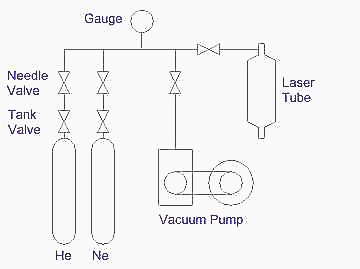 The tube must first be purged of impurities – on my original attempt this was easier said than done considering that the single-stage pump employed (a belt-driven cenco pump) could likely only attain an ultimate vacuum level of 0.10 torr. To clean the tube of impurities I backfilled to 100 torr with pure helium, pumped the tube down to 1-2 torr, and ran the tube (from the regular HeNe power supply) for a few minutes to heat it which drives adhering gases off the elements of the tube. The tube was then opened to the vacuum pump and the contaminated helium pumped out. This cycle was repeated many times (five or six) until the pink helium discharge remains pink after a minute of discharge – shades of blue or violet in the discharge indicate the presence of nitrogen or oxygen. Oxygen is liberated from tube elements such as the aluminum cathode as it heats and its presence indicates that further helium flushing cycles are required however nitrogen may indicate the presence of an outright leak. Liberal application of melted vacuum wax to suspect connections usually solves this problem – melt the wax in a tin can and apply it using a small brush. If a better vacuum pump, such as a dual-stage pump capable of an ultimate vacuum of 1*10-3 torr is employed, one might determine that leaks are plugged to a sufficient level when the entire tube is evacuated to the point where all discharge stops (i.e. the system is capable of pressures of under 2*10-3 torr at which point discharge is not possible) and stays dark when sealed. If such a tube were sealed (using the valve on the tube stem) and the discharge started again, one might well assume a leak (or a large quantity of outgassing) … without an RGA (mass spectrometer) one might use a spectroscope to view the discharge to determine the source of the new gas (either oxygen or nitrogen). In my case (using a single-stage pump), the pump was incapable of evacuating the tube to the point of extinguishing discharge so vacuum leak testing had to be done “the hard way”.
After the tube has been sufficiently cleaned (and leaks in the system, even small ones, patched) the tube was ready for filling with the helium-neon gas mixture. I began by overfilling the tube with 25 torr of neon and 250 torr of helium (10:1 ratio for He:Ne) since these pressures could be accurately read on the gauge (pressures below 10 torr were impossible to read accurately on the mechanical gauge). I then opened the valve to the vacuum pump until the pressure in the tube was reduced enough (lasing starts below 4 torr and optimal pressure is about 1.8 torr) and the laser produces an output beam. The tube may then be sealed via the valve on the tube. Using the rather crude vacuum system described I had been able to reprocess a glass Metrologic tube however it ran sealed for only a few minutes before lasing ceases … likely due to impurities collecting in the tube (everything from oxides from the electrodes to outgassing from the epoxy. Water vapour is particularly toxic to a HeNe laser). Do not expect a tube reprocessed in this manner to last for a long time, but it might be useful for experimentation.
A More Refined Process …
While teaching thin-film and high-vacuum physics at the college, I had access to extremely high-quality vacuum equipment. I developed the following process as a laboratory in which students evacuated and filled a HeNe laser tube allowing them the experience of using high-vacuum equipment and practicing skills in determining contamination sources using a mass spectrometer.
In order to reprocess a tube it was first opened and a vacuum fitting attached. On the newer Melles Griot tube employed (05-LHR-099) this connection was made to the gas port on the tube which protrudes 5-6mm on the metal end cap: the tube was opened using a Dremel tool and a 1/4″ OD copper tube slipped over the opened port. Silver solder is then used to make the connection.
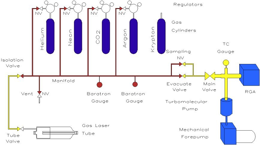
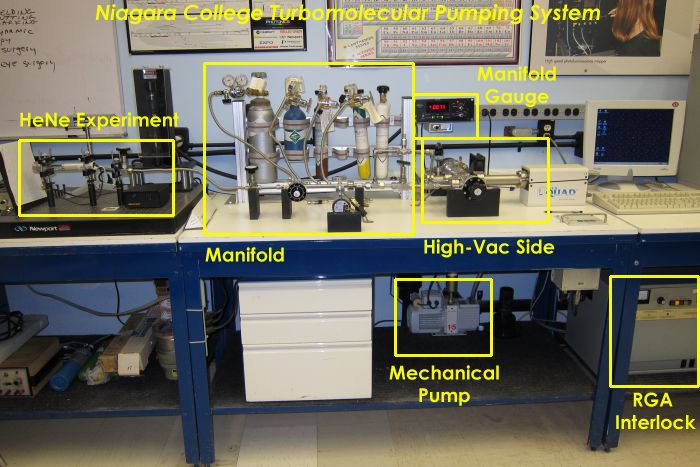
The vacuum system employed uses a turbomolecular pump to allow high vacuum, better than 10-6 torr, to be obtained. The pump-down sequence is similar to that described previously however after each ‘cleaning’ cycle the tube is pumped-down as far as possible to remove as much contaminated residual gas as possible – the gas discharge extinguished completely. The system includes a mechanical roughing pump, an Edwards EXT turbomolecular pump, and a host of valving including a gas manifold. Gas pressures were measured using dual Baratron capacitance manometers (extremely accurate in a mixed-gas environment) and for analysis of the remaining gas in the tube an SRS RGA200 residual gas analyzer (RGA) was attached to the system. Gases were UHP or research grade.
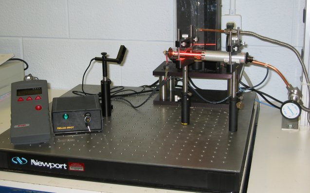
The tube does indeed lase when repumped with power levels of over 2mW (for a tube rated originally at 5mW) achieved. One would not expect to obtain maximum power since a mixture of natural neon (containing 9.6% of 22Ne and the rest 20Ne isotopes) was employed – high performance commercial tubes are filled with isotopically-pure neon gas. Monitored with the RGA, the tube was flushed until ultimate purity was achieved: multiple flushes with research grade helium were performed until the appearance of water vapour and hydrogen contamination in the tube were minimal. The tube was then filled to overpressure (10 torr) with a mixture of helium and neon and pressure reduced to the optimum value somewhere between 2 and 4 torr. Pressure is read on a Baratron gauge which reads gas pressures independent of the actual gas involved (many vacuum gauges like thermocouple gauges must be compensated for the specific gas involved).
With proper flushing (which takes several hours) performance is good as is lifetime. I had one tube which, when isolated from the vacuum system (using the valve evident in the photo), operated for over an hour with a power decrease of only 5% evident! The next day the tube ran fine, again with power approaching that of the previous day. And yes, the valve held vacuum all that time (it was a Nupro valve designed for high-vacuum work) – cheaper valves would likely have leaked a little overnight causing the laser to fail by morning.
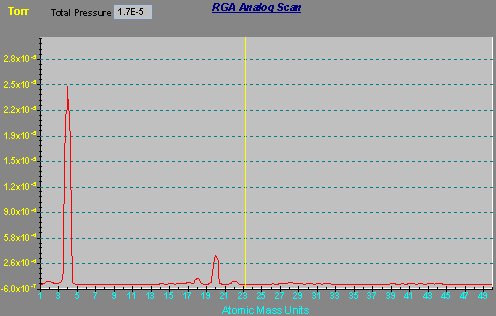
A working gas mix is seen here as analyzed using an RGA (Residual Gas Analyzer / Mass Spectrometer). The He:Ne ratio (found by ratioing the pressure peaks at 4 amu and 20 amu) is 10:1. Also visible here is the 22Ne isotope and various residual contaiminants such as hydrogen (2 amu) and water vapour (18 amu). Pressures shown on the RGA are reduced (by necessity for operation of the RGA) and scale linearly. The actual tube pressure was about 2.0 torr for peak output. It was found that the He:Ne ratio can vary from a low of 7:1 to a high of about 12:1 or even 15:1. High helium concentrations favour higher tube pressures allowing the tube to lase at pressures of 5 torr or more (my students once ran the tube at 40:1) with such high concentrations working at all by allowing a reasonable E/p ratio (with ‘p’ being the partial pressure of neon in the gas mix) – of course power output suffers in the process. At lower ratios, considerably more helium than neon is still required to ensure that there are adequate excited helium atoms available to pump neon to the upper lasing levels via the collisional transfer process – a minimum ratio of about 4:1 was found.
References
[1] Nondestructive Analysis for HeNe Lasers, A.E. Ahearn & R.E. Horstmann, IBM Journal of Research and Development, Vol. 23, No. 2, March 1979
Videos
HeNe Tube Reprocessing a video outlining the lab I developed
Argon Gas Lasers
Presented are some experiments with argon lasers, both CW and pulsed.
Background
The first ion laser was the mercury ion laser discovered by W. Earl Bell of Spectra Physics in 1965. This laser, in which the active lasing species in mercury vapour in a buffer of helium, emits at 615nm in the orange, 568nm in the green, and at two IR wavelengths. It was a pulsed laser in which lasing was determined to occur during the afterglow – the time after the main discharge had occurred. This suggested that the mercury ion laser was unlikely to operate in CW mode. While investigating the nature of this laser researchers tried neon and then argon as buffer gases (instead of helium). When argon was used a strange new line at 488nm appeared and would show-up when even only a trace of argon was present in the tube. It was noted in an early report that welding grade argon was used as the buffer gas. As well as the discovery of the argon-ion laser oxygen (O+) was also discovered to lase by accident at the same time when four lines in the blue-violet appeared when oxygen was liberated by electrodes used in the tube.
The environment inside an ion laser tube was hardly an easy one to tame. High currents required for CW operation led to strong pumping of ions towards the cathode region of the tube. Pressure gradients occurred which led to instabilities in the discharge. A gas return path was incorporated into these tubes to equalize pressures to solve this. Another problem was sputtering which occurs as the tube runs. This effect buries argon atoms lowering tube pressure. A large buffer volume (for small tubes) or an active gas refill system (for large tubes) was required to add gas to the tube and raise the pressure. Modern ion lasers have a fill system like this which monitors tube voltage and inject gas from a high pressure chamber when it drops (which indicates a pressure drop) via a solenoid valve. Ion tubes also run incredibly HOT. A large argon laser might have a tube voltage of 260 VDC and a current of 40A. That means over 10,000 Watts of HEAT must be dissipated in a relatively small volume. Glass tubes cannot stand the stress of this kind of heat and so ceramic must be used. The discharge in the tube is usually confined by discs of refractory metals such as tungsten which center the discharge to the actual bore: only about 1mm!.
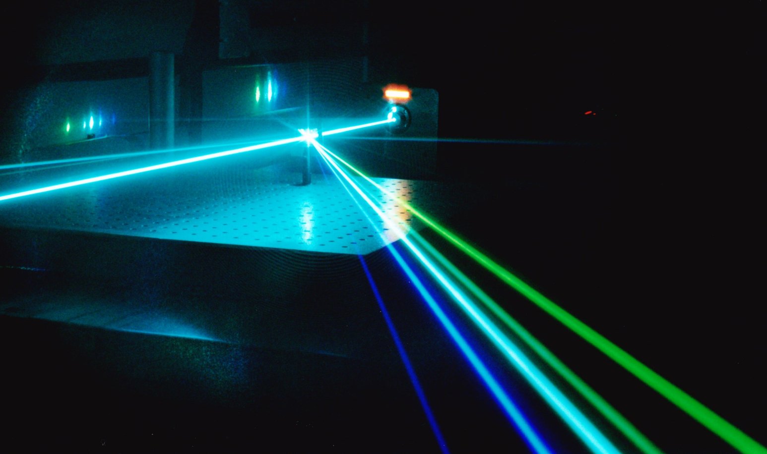 Practically, most argon lasers are huge water-cooled behemoths – I had several in my lab including a Coherent Innova-90 (pictured to the left) which produced an output power of seven watts on several lines in the blue to violet region while consuming 208V/3-phase/45A per phase and a larger Coherent Innova-200 that ran from 440 Volt/3-phase/70A per phase, consumed 6.5 gallons per minute of cooling water, and output up to 25 watts. These large beasts are difficult to run in anything but a large commercial setting as 3-phase power is required at these power levels.
Small argons exist as well – these are forced air cooled and resemble an overgrown HeNe tube although their electrical characteristics and construction are radically different. Some have attached optics (like a HeNe) and others Brewster windows on the tube with separate optics.
Powering Small Air-Cooled Tubes (CW)
Small air-cooled ion laser tubes resemble an overgrown HeNe tube. They are made of ceramic to take the intense heat generated by the discharge (something you never had to worry about with a HeNe tube) and have a large number of cooling fins surrounding the tube. A large volume of air (over 300 cfm) is blown past the tube – failure of this air flow will result in rapid tube failure!. For most tubes it is supplied by a small squirrel-cage type blower. Tubes such as this are available on the surplus market.
Unlike the HeNe laser ion lasers have hot cathodes (the tube itself , electrically,resembles an old vacuum-tube diode). The cathode is heated by a 2.5 volt, 10 Amp AC transformer. The filament/cathode also serves as the negative terminal of the tube. To keep the cathode from eroding an AC source is required and the filament transformer must be center-tapped.
Ion laser tubes run at low voltages compared to a HeNe laser. In the case of a small tube as outlined on this page between 100 and 120 volts DC appears across the tube when lit. Current through the arc is quite high though at 8 to 10 Amps (yes amps, not milliamps). Most lasers of this type (as well as larger water-cooled types) use the AC line directly, rectified and filtered, as the main power source. This means that all parts of the tube are electrically LIVE – nothing is ground! You can see why this isn’t a good first-project. On the other hand, a much smaller (and safer) pulsed supply (further below) may be used to power-up ion laser tubes.
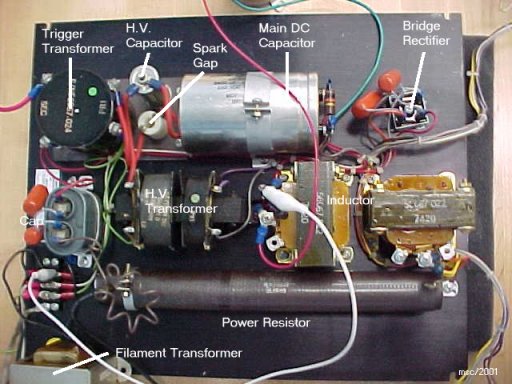
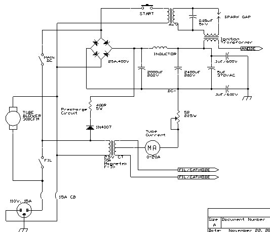 In my case, I modified an arc lamp supply to power a small argon laser tube. Arc lamps used for illumination have similar characteristics to an ion laser tube. The power supply begins by rectifying the 120VAC line then filtering it with a pi-LC filter consisting of two large capacitors and an inductor. Current limiting is supplied by a 5-ohm, 225-watt adjustable resistor (although a transistor pass-bank allows true regulation and is a better approach and invariably employed in commercial units).
Argon tubes will not ignite at 100 volts – over 10 kV is required to ionize the gas in the tube and start the arc. In most lasers this is done by a circuit which boosts the line to between 600 and 800 volts and then a capacitor discharge circuit blasts this through a series transformer which results in a huge high-voltage pulse being presented to the tube anode. Although this works, and might well be the simplest method, it also results in cumulative damage to the laser cathode. The start pulse can have significant energy which may well result in destruction of a small-piece of cathode each time it is started. The arc lamp supply used here impresses a low-current high-frequency high-voltage on the anode to ionize the tube. In its simplest form, the ignitor resembles a Tesla coil: a high-voltage (AC) transformer at about 4kV charges a capacitor which then discharges at high frequency through a spark gap to a resonant coil. The secondary of the coil then show a very high voltage but at a high frequency and low current – just the thing to ignite the arc safely! The ignitor consists of a 4kV transformer, a 0.05μF/5kV capacitor, a 3mm spark gap, and a trigger coil. The secondary of the coil must withstand the 10A or so which power the tube and must have high dielectric value as the voltages produced are quite high. It is possible to wind such a transformer by oneself in a manner similar to making a small Tesla coil. Be sure the secondary is wound with at least #16 gauge wire. The ignitor works quite well and needs to be activated for only a fraction of a second to start the tube.
One must be careful to prevent any high-frequency component from the start circuit from entering the rest of the power supply. The electrolytic alone may not be enough as they tend to have large internal inductances (as evident from the fact they do not work for dye lasers). To ensure all was safe a small (5μF, 370 VAC) capacitor is used as a bypass cap across the DC output of the main supply. These AC capacitors are paper/oil types and have low inductances. They will easily bypass any high frequency components which might otherwise wreak havoc in the supply.
Finally, it is worth mentioning that a bleeder resistor should be placed across all capacitors capable of storing a lethal charge. These resistors are visible across the large electrolytic capacitors in the photo of the original power supply. Some commercial supplies go one step further in adding a “dump” resistor whereby upon deenergizing the supply (either by selection or by tripping an interlock) the relay shunts a low-value resistor across the capacitor.
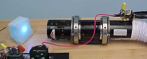 In a first test a Cyonics/Uniphase tube was used. These tubes are prepackaged in a cylindrical housing and feature attached optics so alignment is unnecessary. Air is taken from the rear of the housing via a blower using white plastic tubing used for electric clothes dryers. This particular tube outputs about 30mW at 488nm (in the blue). Other tubes are available on the surplus market with a variety of lines (some are multiline producing over 7 lines simultaneously) and powers (up to 250mW). Also used with this supply was an ILT mixed-gas argon-krypton tube. This particular laser, however, had a high tube pressure (probably from years of non-use) and so exhibited only a single dominant 488nm argon blue line and not all of the krypton lines as hoped.
Several items must be improved and/or added before the power supply is ready for ‘prime time’ including the addition of a fail-safe interlock system and a true current regulator. In the case of interlocks they ARE required for safety of the operator as well as protection of the (expensive) tube. ALL ion tubes are equipped with a thermal sensor which opens when tube temp is exceeded. Never knowing _precisely_ if the air flow is high enough (and what happens if the blower intake is accidently blocked?) it is mandatory to shutdown the tube if this sensor is activated. As well, covers on the tube and power supply must be interlocked to prevent one careless mistake from becoming one’s last! Finally an external interlock is mandated by Class-IIIb regulations and must be added to the chain.
Current regulation is important to prolong the life of the tube, and even during normal operation to prevent “runaway” in which current can climb without limits eventually destroying the tube. Many ‘simple’ argon supplies do not use a true regulator but rather a simple pass bank allowing adjustment of tube current. Commercial supplies feature a full control loop with current and light feedback to truly regulate the tube’s current. A simple linear pass-bank can be built using an array of six paralleled 2N3055 NPN power transistors on a large fan-cooled heatsink.
For more info on various power supply designs see Sam’s Laser FAQ.
Pulsed Operation
It was desired to construct a grounded-cathode pulsed power supply for use when testing and reprocessing tubes in the lab. Conventional CW supplies, including the one above, have the cathode ‘floating’ below ground potential. When reprocessing a tube such as an ALC 60X tube, a copper stem is welded to the existing pump-out tube on the cathode making the cathode ground. As well, at the high continuous currents available from a CW supply, faults, including those caused by large pressure variations, can be catastrophic whereas a pulsed supply has a much more limited capacity for destruction!.
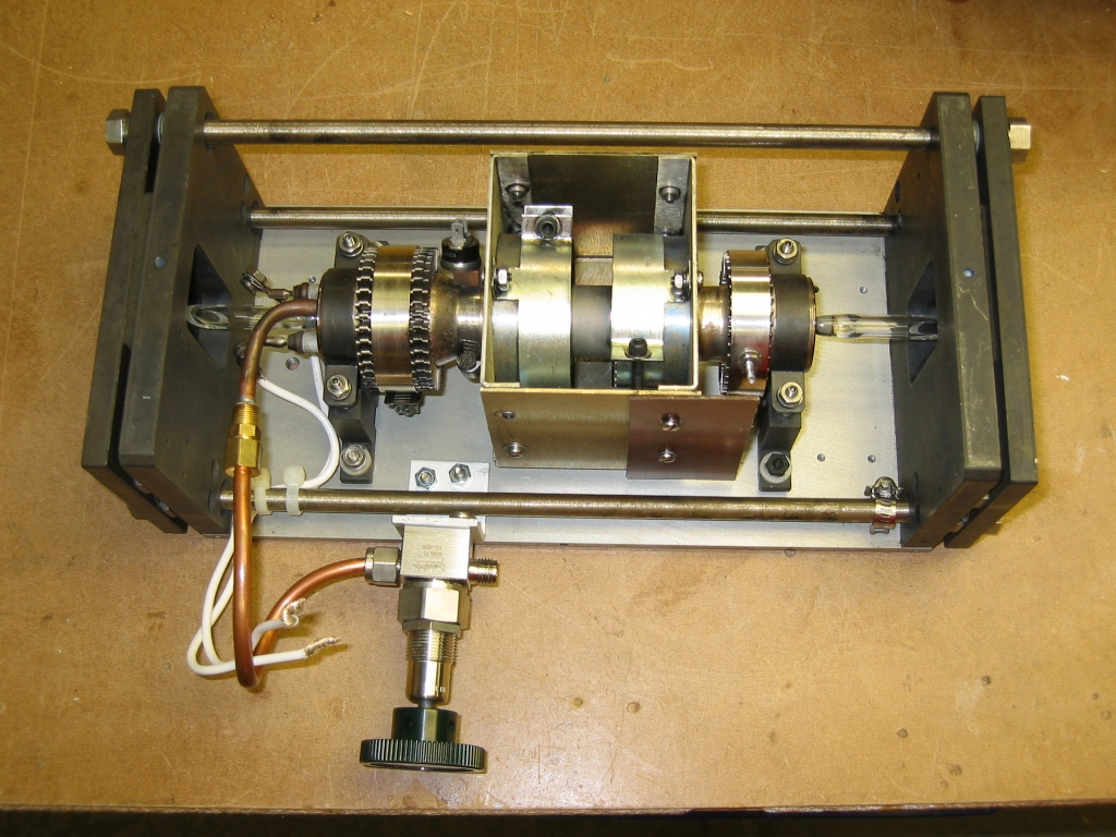 The first attempt was to use a high-voltage supply similar to the design presented in the Amateur Scientist design [1] except with a heated cathode (This design was also suggested in SAM’s laser FAQ). High voltages of up to 10kV were used to charge capacitors of 0.1μF to 0.35μF which then discharged through the tube when the breakdown voltage was reached. Current was measured by inserting a 1Ω shunt between the center-tap of the filament transformer and ground (negative). Peak currents of over 35A were recorded which should essentially guarantee lasing action (threshold current for most tubes is around 4A) however no lasing output was detected at all! A typical current pulse (0.1μF capacitor, 200Ω series resistance), measured via the shunt, featured a pulse width (where current was > 10A) of 183nS, a rise-time of 55nS, fall time of 450nS, and a peak current of 17.4 A. Still, no lasing output was detected. An ALC 60X tube was modified with a valve allowing repumping (see below). The tube was evacuated to better than 1*10-6 torr and refilled with UHP argon gas over the pressure range from 10mTorr to 280mTorr but again, lasing was not detected (despite the fact that at a pressure of 150mTorr peak current was measured to exceed 40A). Relaxation oscillators employing high voltage and low capacitances do not appear to be the correct approach.
A Practical Pulsed Argon Laser Power Supply
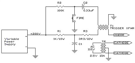 It is known that even an overpressured tube will blink intermittently during starting using a commercial supply (as the capacitors in the supply discharge into the tube) and a pulsed supply was designed along these lines. The supply, seen in the diagram, charges a main capacitor from a variable power supply to about 200V. This is insufficient to ignite the tube, though, so a series trigger transformer is used to supply a high-voltage pulse to the anode to start the discharge in a manner similar to that employed with the CW supply.
When the pushbutton is pressed, the tube ionizes and current flows from the capacitor as a relatively long (quasi-CW, >1ms) pulse of current. No attempt was made to reduce inductances within the discharge path since the laser is known to operate in CW mode regardless and so discharge time is unimportant. With 200V of DC on the main capacitor, and the trigger transformer capable of supplying a 3mm spark in free-air, the system works reliably giving a pulse of laser output each time the button is pressed (so long as time is allowed between firings for the capacitor to charge). Like the CW supply, a Cyonics/Uniphase tube was employed for the first test of this supply.
It was curious to note that there is a minimum capacitance at which the laser will operate. Using a 10μF capacitor lasing was not observed even when the operating voltage was increased to 400V! Current monitoring (via a shunt on the center-tap of the transformer again) revealed currents of over 20A peak. When a larger capacitor was employed (47μF was found to be the minimum for lasing), the current pulse was not appreciably larger (in many cases smaller) however the pulse was, as expected, wider! Apparently, the success or failure of lasing depends on the width of the pulse and not necessarily the peak current.
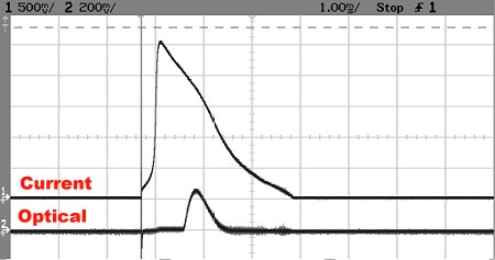 Capacitances (all electrolytic) of 47μF, 82μF, and 510μF were used with progressively larger output pulses. In this example an 82μF capacitor was employed at a voltage of 200V. A current shunt of 0.25Ω was used so that a peak current of 10A is seen here. The development of the light pulse, as measured using a Newport SL-818 power meter, is shown on the lower trace. Clearly, the production of the light pulse does NOT coincide with the current peak, but occurs 500μs later. This same behaviour was seen when the 510μF capacitor was employed which yielded 16A peak currents and much larger optical output however the delay was still seen. I do not believe the delay can be attributed to the power measuring instrument and such delays have been previously observed [5][6] although never to this extent (although one must realize that the pressure in the tube is much larger than one designed solely for pulsed operation).
It was important, as well, to heat the cathode properly. Cyonics/Uniphase tubes require less filament current so that the measured voltage across the filament at the tube connections was 2.0V. With an Omnichrome-532 tube, the same filament transformer yielded only 1.5V and was clearly being overloaded (it was overheating). An inadequately heated cathode such as this results in unreliable firing of the tube (especially when warm) and will ultimately result in cathode failure. A new 3V 50A filament transformer (Hammond 165Z3) was then used with these tubes.
This supply has been useful for testing reprocessed tubes during the gas fill process since it allows a grounded-cathode configuration (see below).
While it is not suggested that the casual amateur refill an ion laser tube, tubes can be evacuated and reprocessed using a high-vacuum system and even used with gases other than argon. In a manner similar to that described on this page for repumping HeNe tubes, an ALC-60X was carefully opened in a class-1000 cleanroom and the original filling stem silver-soldered onto a 1/4″ copper tube. A Swagelok/Nupro SS-4BK high-vacuum valve was used to isolate the tube from the vacuum system. This arrangement allows for the reprocessing of the tube with argon as well as other gases (e.g. krypton and even oxygen). It is also possible to employ the tube in fast-discharge experiments such as that used with the neon laser. With that particular laser, a HeNe tube was filled with pure neon gas and pulsed with a fast-rising current. After several minutes of use, however, the internal mirrors on the HeNe tube were visibly damaged by the high-energy plasma. Use of a, ion laser tube such as a 60X is preferable since it lacks internal mirrors with their easily-damaged coatings instead featuring quartz windows at Brewster’s angle.
When the filling stem is connected to a vacuum system, electrically, the cathode is now at ground potential and so a commercial CW supply cannot be used. It is intended that either an isolated supply (with the negative terminal at ground potential) or a pulsed supply, such as that described above, be used with the system. Some unusual tubes (e.g. an ILT) have the filling stem from the anode so a grounded-anode (positive ground) power supply system must be used since the anode would be connected to the grounded vacuum system.
A 60X tube was used with a pulsed supply identical to that described on this page using a 510μF capacitor and 3.3Ω series resistance. Using the maximum available voltage of 400 volts, lasing at 488nm (‘blue’ optics were installed on the laser which do not support the green line) was observed over a pressure range of 600mTorr to 350 mTorr of pure (UHP grade) argon gas.
While it is not suggested that the casual amateur refill an ion laser tube, tubes can be evacuated and reprocessed using a high-vacuum system and even used with gases other than argon. The tube below, an ALC-60X, was carefully opened in a class-1000 cleanroom and the original filling stem silver-soldered onto a 1/4″ copper tube. A Swagelok/Nupro SS-4BK high-vacuum valve is used to isolate the tube from the vacuum system.
This arrangement allows for the reprocessing of the tube with argon as well as other gases (e.g. krypton and even oxygen [2]). It is also possible to employ the tube in fast-discharge experiments such as that used with the neon laser. With that particular laser, a HeNe tube was filled with pure neon gas and pulsed with a fast-rising current. After several minutes of use, however, the internal mirrors on the tube were visibly damaged by the high-energy plasma. Use of a tube such as this (an ion laser tube) is preferable since it lacks internal mirrors with their easily-damaged coatings instead featuring quartz windows at Brewster’s angle.
When the filling stem is connected to a vacuum system, electrically, the cathode is now at ground potential and so a commercial CW supply cannot be used. It is intended that either an isolated supply (with the negative terminal at ground potential) or a pulsed supply, such as that described above, be used with the system. Some unusual tubes (e.g. an ILT) have the filling stem from the anode so a grounded-anode (positive ground) power supply system must be used since the anode would be connected to the grounded vacuum system.
A 60X tube was used with a pulsed supply identical to that described on this page using a 510μF capacitor and 3.3Ω series resistance. Using the maximum available voltage of 400 volts, lasing at 488nm (‘blue’ optics were installed on the laser which do not support the green line) was observed over a pressure range of 600mTorr to 350 mTorr of pure (UHP grade) argon gas.
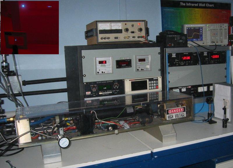 Since the average power is low, this supply can be used with any argon laser tube, large or small. For a student lab in which a laser tube was repumped, a water-cooled Lexel-98 laser tube was operated in pulsed mode using such a supply. This larger-frame ion laser tube (originally rated at 2W CW) was repumped as an experiment in E/P ratio for a Vacuum and Thin-film technology course (PHTN1432) in which students experiment with various pressure ranges to determine the optimal E/p ratio. This particular tube had a cut gas line which connected the tube to a large ballast volume beside the tube in the head. A short length of stainless tubing was attached to the tube using Torr-Seal epoxy (which has low vapour pressure) and was connected to a vacuum system employing a turbomolecular pump (described under the “helium-neon repump” experiments on this page). Water cooling with flowing tap water was used as the original tube featured a cooled ceramic tube and magnet.
The complete experimental setup showing the Lexel laser as well as various vacuum gauges for the vacuum system in the background are shown in the photo. On top of the 19-inch rack sits the power supply and, to the right, an oscilloscope to capture the amplitude and shape of the laser pulse.
The tube was opened to atmosphere during connection of the gas valve and during the first pumpdown it was observed to liberate a huge amount of gas when heated – enough to raise the pressure from zero to over 200mTorr in a closed system. The cathode was subsequently outgassed by heating it with the pump running “full open” until the pressure was not seen to rise again when the system was sealed from the pump – this ‘bake-out’ procedure took a day to accomplish! After that, the tube could be filled with the required 50mTorr of argon gas, sealed, and would operate reliably.
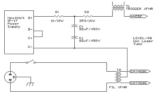 The tube was powered using a testing supply as outlined above. A 3VAC/25A filament transformer (scavenged from an old Coherent CR-6 ion laser head) powers the heated cathode. The main capacitor bank consists of two capacitors in series to handle the voltages used. A dual power supply, a Heathkit IP-17 used originally to power vacuum tube circuits, was used. The two outputs, “B+” variable from 0 to 400V and “C-” variable from 0 to 150V, are used in series to charge the capacitors (which can then be charged to a potential of 550V). By using a split supply the “B+” supply alone is used to charge the trigger supply (two 1μF/400V capacitors in parallel, as scavenged from the original Lexel-98 power supply) preventing that system from being charged to more than 400V.
In addition to the anode supply, a separate regulated supply is used to power the coaxial magnet which consumes 1A at about 80V. A simple cooling system consisting of a garden-pond pump and a five-gallon pail of water is used to flow water through the magnet and cathode (the cathode, especially, requires cooling).
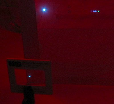 After careful alignment of the optics, and repeated flushing to eliminate impurities emanating from the cathode, the tube was found to lase reliably at pressures between 40mTorr to 70mTorr (with an anode voltage of 500V) as predicted by theory (With a tube length of 50cm and an anode voltage of 500V, argon, with an E/P of around 200 V/cm-torr, should operate around 50mTorr). The magnet was also found to be essential for reliable output as well.
The output of the Lexel laser is seen here split by a diffraction grating. The bright 514nm emission is seen to the far right as well as the 488nm emission in the middle of the spectrum.
References
[1] How to construct an argon gas laser with outputs at several wavelengths
Scientific American, Amateur Scientist Column, Feb 1969
A pulsed argon laser is constructed.
[2] A Cold Cathode pulsed gas laser R.K. Lomnes & J.C.W. Taylor
Review Of Scientific Instruments, Vol. 42, No. 6, 1971, pp. 766
A pulsed experimental laser. Details the use of Argon, Krypton, Xenon, and Oxygen.
[3] Laser Oscillation in singly ionized argon in the visible spectrum William B. Bridges
Applied Physics Letters, Vol. 4, No. 7, 1964, pp. 128
A Pulsed DC argon laser is described
[4] Superradiance, Excitation Mechanisms, and Quasi-CW oscillations in the Visible Ar+ laser W.R. Bennett Jr., et al
Applied Physics Letters, Vol. 4, No. 10, 1964, pp. 180
A CW Argon laser is described
[5] Direct Gain Measurement of a pulsed argon-ion laser
S.M. Jarrett & G.C. Barker
Journal Of Applied Physics, Vol. 39, No. 10, 1968, pp. 4845
A method is presented to measure the gain of an argon laser using a CW argon beam – gives gain figures for several lines
[6] Visible and UV Laser Oscillation at 118 Wavelengths …
W.B. Bridges and A.N. Chester
Applied Optics, Vol. 4, No. 5, 1965, pp. 573
Outlines laser oscillation observed in ionized neon, argon, krypton, xenon, and oxygen. Also discussed quantum mechanics and quantum excitation mechanisms of these lasers.
Videos
While I was a professor at Niagara College I produced a series of videos in 2020 while teaching remotely due to the CoVid pandemic. They might be interesting as they outline important procedures such as optical alignment.
- Gas Laser Optics 1 detailing alignment of the optics of a HeNe laser (a Melles-Griot WPR-252)
- Gas Laser Optics 2 detailing measurement of gain using a HeNe laser with separate optics