A look at what is likely the oldest surviving steam engine in the world 1
I have had the opportunity to visit the Henry Ford Museum in Dearborne, Michigan several times. This museum houses an immense collection of interesting items covering the history of key technologies related to transportation and one of the most fascinating items in the collection is the oldest surviving Newcomen engine. Housed at the back of the immense museum (which was built around some of the engines housed here), this machine played a pivotal role in ushering-in the industrial revolution around 1760.
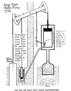
 The Newcomen Steam engine, the predecessor to the Watt engine, is one of the most interesting pieces of technology developed during the 1700’s. This engine along with Watt’s are called “atmospheric engines” because the steam was under only slight pressure (5 psi). The real driving force of these engines was a vacuum created when steam is condensed back into water, or rather the pressure of the atmosphere on top of the cylinder which drives the piston downward into that vacuum.
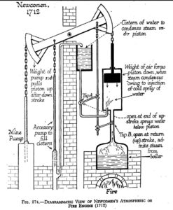
The diagram at right2 explains the principle of operation of a Newcomen engine. In this drawing of a primitive engine (1712), the boiler sits directly below the cylinder. Steam is first admitted from the boiler to the cylinder. The pump end of the beam is heavier than the piston so the piston rises and the pump falls during this action. When the piston reaches the top, water is sprayed into the cylinder to cool the steam and hence form a vacuum in the cylinder. The piston is pushed down into the cylinder by the weight of the air on top of it (15 pounds per square inch of piston area) and the cycle is started again.
A Real Newcomen Engine from 1760
 The following photographs are of the oldest surviving Newcomen engine. This engine, known as ‘Fairbottom Bobs’, was used to drain water from the Cannel coal pits close to the River Medlock, about half a mile from Park Bridge, Ashton under Lyne, in England. The name arose from the bobbing motion of the wooden beam. The engine, built in 1760, was used until 1834 (although Herbert Morton who moved the engine for Ford, stated that the pit it served closed in 18276). Newcomen engines first appeared around 1712 so this particular engine represents a ‘perfected’ design including, for example, a boiler feed (to keep it topped-up with water), an accessory pump to constantly keep the cistern filled, and a water seal at the top of the cylinder.
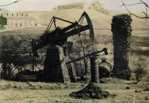
This photograph, taken in the 1880s, shows the engine as installed, but already in a state of decay since it was unused for fifty years. This photo was copied from the Ashton-under-Lyne site, in north-west England, where the original engine sat. By the 1920s the engine had been neglected and had fallen into extreme disrepair. It was bought by Henry Ford in 1929 and brought to America where it is housed today at the Henry Ford Museum in Dearborn, Michigan, displayed alongside other machines which helped bring about change. Total output power from this engine is approximately 20 horsepower. The engine ran at an estimated 14 strokes per minute, had a bore of 28 inches, and a stroke of 72 inches.
 I was told by a visitor to this site (Richard Holliday), who lives in the area, that the mine was about 200 feet deep. It mined the Cannel mines, which were part of the Fairbottom group of coal mines (the Mary, Park, and possibly the Stubbs mine). Bobs was part of the Fairbottom group of mines which included Fairbottom / bridge pit / Coperas house colliery (later woodpark) and the Bardsley pit … all were coal mines in the middle coal measures, the only one to survive into the 20th century was woodpark colliery which closed in 1957 and was 510 yards deep. Today (2008), the area is pictured below (Photo by Richard). Clearly shown are the 2 capped shafts and the base of the chimney.
It can be assumed that Fairbottom Bobs was a two stage pump because of the position of the coal seams – mines would be pumped up to a lodge in the Park/Stubbs mine in the first lift then to the surface in the second lift as Fairbottom was the lowest and latest seam to be worked in the area.
Nearby the area of Bobs was a pit called Rocher Vale which also had an early beam engine, and in the area around Bobs there are 15 old shafts, perhaps many more. Ninety percent of these shafts were single shaft pits dug prior to 1800 and the Bobs mine used a few of these as air shafts. It was also reported that about 50 feet west of the shafts shown in the photograph of the area today (taken in 2008) in the river bed there are several jets of rusty water gushing up through cracks in the underlying rock beds as the flooded coal workings are at a higher elevation and the water is under great pressure … staining the river orange.
The engine shown here had an output power of approximately 14.9kW (20hp) and operated at 14 strokes per minute (and so the piston cycles once every four seconds – quite fast for the weight of the engine. It had a 28 inch cylinder bore and a stroke of 72 inches.
The Engine Today …
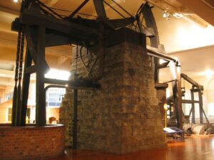
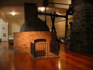
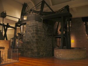 The entire engine consists of a round boiler (to the left, as seen in the photo below) driving the main cylinder which sits behind the massive stone support for the beam. At the front of the beam is a two-stage pump used to pump water from the mine. This engine, from 1760, is a more advanced model than the one in the explanatory diagram and features an auxiliary pump which filled a reservoir at the top of the support column to provide both the water spray to condense steam in the cylinder as well as an automatic boiler feed mechanism to keep the boiler filled with water.
“Original ??” … due to the extremely decayed state of the machine when brought to the museum, some elements of the engine were rebuilt for the display. The original stone column which supports the beam was saved, but the wooden beam itself was rotted and so the one on display is a reproduction. Brickwork, like the short circular wall around the pump shaft, was reconstructed at the museum to portray the engine in it’s original state. Finally, the boiler is not original but was scavenged from a different engine. Old photographs from the 1920’s show Henry Ford on the site of the old engine just prior to removal with the old boiler beside the engine: it was cylindrical in shape and the original was, as evident in the old photo, rusted beyond saving (Although even that may not have been the truly “original” since the engine may have been moved once before)1,3.
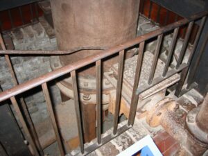
 Linkages leading down to the mine pumps (on the far left) are visible here. The water pump which this engine drove was a ganged, side-by-side, set of force pumps. A force pump uses a piston, sucking water from the mine into the piston and expelling it upwards. The suction stroke is only as long as the piston length, and is less than 30 feet, so water can be pumped from great depths (30 feet was the limit of pumps which came before this one).
To the right of the mine pumps (and left of the large column) is the auxiliary reservoir pump. This pump keeps the reservoir on top of the support column filled: water in the reservoir is used for cylinder water injection (to condense the steam) as well as to replenish the boiler. In addition to these functions, a small leak from this reservoir floods the top of the piston with water – in another spark of mechanical genius, Newcomen used water to seal the piston against leaks. Excess water flooding the piston simply overflowed from the top of the cylinder into the well underneath.
 Although this is not the original boiler1 (since several photographs of the engine at it’s original site show a cylindrical boiler), this example would be historically correct for an engine of this type.
The idea of using a round boiler to hold the pressure was originally taken from beer brewers who used round vessels which could withstand pressure better than other shapes. Brick also helps concentrate heat from the fire to produce the immense amount of steam required by the engine. Even so, the Newcomen engine was inefficient and consumed copious quantities of fuel during operation.
At the top of this particular boiler (on the left) a pressure relief valve can be seen as well as a feed system on the right to keep the water level topped-up. On the earliest Newcomen engines the the piston sat directly atop the boiler but on later engines such as this the boiler was separate and was connected via a pipe to carry steam to the engine.
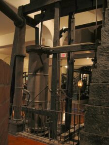 Mounted beside the great cylinder (on the boiler side) is the steam inlet valve which admitted steam into the cylinder when it was at the bottom of the stroke. The valve, in the square box at the bottom of the vertical feed pipe, was actuated via the steel rod seen leading to the right. As the piston pressed into the cylinder a secondary arm, attached to the beam, also lowered – on this arm was a pin which tripped the valve ‘open’ allowing steam into the cylinder. The piston raised as a result of the inrushing steam and a second pin on the arm closed the inlet valve when the piston reached to top of the stroke.
This “Y” actuator, which toggled to allow steam into the cylinder then toggled back to close the valve, was an inspiration of Newcomen’s4 which allowed completely automatic operation of the engine (unlike, for example, Savery’s earlier pumping engine which required an operator to constantly open and close valves). Precision was required to make it work properly, and in the 1700’s it would have been machined entirely by hand.
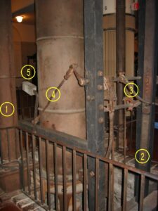 A close-up of the “Y” actuator on this engine reveals how it operates. As shown on display, the steam valve [1] is open and the piston near the top of the stroke. The piston moves a little higher, and the push rod [2] shown will raise a pin which will in turn flip the curved metal lever [3] upwards pushing the rod on the left side [4] downward. As the rod pushes downward, the weight on the end of the valve [5] will flip backwards (to the left, as shown) closing the steam inlet valve and keeping it closed while the water injection valve is opened and the piston falls into the cylinder. When the piston is at the bottom, another pin will push the curved lever down which ultimately will cause the weight on the far left side to flip forward and hold the steam valve open until the maximum stroke is reached again.
 A similar valve to the steam inlet valve, on the other side of the large cylinder, injected water from a reservoir atop the beam support. Again, pins on the push rod tripped the valve open (at the top of the stroke) momentarily injecting a small amount of water to condense steam inside the cylinder.The valve is seen in this photo along with the pushrod from the left.
More Historical Insight
Although not much documentation exists on Fairbottom Bobs, insight into the Newcomen Engine can be garnered from some documentation of another Newcomen engine, pre-1741, originally used at Church Lawton Manor (Cheshire, England) to pump bring from a salt mine.
Detailed records compiled by Guy Lawton, author of “Church Lawton Manor Court Rolls 1631-1860”5 include the complete cost breakdown for the components of a Newcomen engine. Perhaps the most fascinating part of this list is the fact that many of the components listed can be found on Fairbottom Bobs.
| Component | £ | s | d |
| The Boiler | 14 | 0 | 0 |
| The Brass regular [?regulator] | 4 | 10 | 0 |
| The Cylinder | 26 | 5 | 0 |
| The Pistoll Chain and Brass ring | 4 | 13 | 0 |
| The Centre pin | 1 | 4 | 0 |
| Twenty one Cast metle Barrells | 50 | 0 | 0 |
| Seventy two Yards of Iron Rodds | 3 | 12 | 0 |
| Five Iron Chains | 3 | 0 | 0 |
| The Sinking pipe | 1 | 0 | 0 |
| The Y: Y: | 0 | 5 | 0 |
| The Hanging Y: and Sliding Y: Irons | 0 | 1 | 8 |
| The T: | 0 | 2 | 4 |
| The Six Brass Clacks | 1 | 10 | 0 |
| The Two Cylinder Beams of Wood with Joyes [?Joists] and Boards | 10 | 0 | 0 |
| The two Cistern and Beams | 5 | 0 | 0 |
| The Regulating Beam with two Arches and Spring pinns | 4 | 0 | 0 |
| The Cistern | 3 | 13 | 0 |
| The two Lead pipes and the Brass Cock from the Cisterne to the Cylinder | 1 | 6 | 0 |
| The cup round the Cylinder head and the lead pipe from thence to the hott well | 0 | 10 | 0 |
| The Hott Well | 0 | 9 | 0 |
| The Nine Wooden Trees in the pitt and Jack | 9 | 0 | 0 |
| A Capson [?capstan] and Rope | 1 | 0 | 0 |
| Fire Shovle, rings, Coal Rake, and Fire hookes | 0 | 5 | 0 |
The costs given are in the old British system where 1 pound = 20 shillings, and 1 shillings = 12 pence. The total cost of the engine was 145 pounds in the early 1700’s … not bad considering Newcomen engines were licensed to mine owners at up to 300 pound per year5!
The function of some items in the list is a bit of a guess, however “The Steam Engine of Thomas Newcomen” by Rolt & Allen (1977, Moorland Publishing) offers an excellent description of such engines which may be applied here:
- Early Newcomen engines used a “beehive” boiler with a steam dome in which the main cylinder was situated immediately above. The “regulator” on such an engine was the inlet valve located atop the steam dome which regulated the flow of steam to the cylinder. The engine at the Henry Ford Museum has a different arrangement with a separate boiler.
- The cylinder was a particularly expensive item, especially given that on early engines the inside was not machined smooth requiring a piston seal which required frequent replacement.
- The “Cast metle Barrells” were a mystery until one considers the early pumps which often consisted of multiple barrels (many up to 9 feet in length) which comprise a lift pump of over 200 feet in length. From descriptions of early pumps, these barrels were the actual portion pushed up and down, acting as “pump buckets” which fill with water. Multiple lift segments would have been required since the pressure of air prohibits a single element from lifting beyond 30 feet or so. Water was pushed through a one-way valve (often made of leather) on the downward stroke and pulled upward when the piston (on the opposite end of the beam) was pushed downward into the cylinder by atmospheric force. Several other items on the list such as “Brass Clacks” support this theory – the clacks being length of pipe below a pump barrel with an expanded end into which the clack valve seats.
- The “Y:” was an iron bar of an inverted “Y” shape with a weight on one end. It rocked to and fro opening a valve when required in the cycle and so two such bars were required. The Henry Ford engine has two of these bars – one for the inlet valve and one for the exhaust valve.
- The “hott well” serves as the exhaust for the cylinder into which hot condensed water accumulated in the cylinder is expelled, often through a one-way valve fabricated of leather.
- The “cup round the cylinder” was a rudimentary seal between the piston rod and the top of the cylinder kept wet by water leaked from the cistern.
- The “Pistoll Chains” were likely used to connect the piston and pump rods to the arches on the ends of the great beam and the “Centre pin” the large metal pin serving as a pivot point for the great beam. Conventionally, the pump sat outside the engine house allowing access to the pump itself should the rods need removal.
- In many cases, pump rods were made of timber to save weight. This might well be the “nine trees” mentioned in the component list.
Watt’s Engine
 About 65 years after Newcomen invented this engine, James Watt made an improvement which was to improve the efficiency of the machine. The addition of a second cylinder, a condenser, allowed the main cylinder to run at a reasonably hot temperature without cooling off and pre-condensing the steam. This was the main problem with Newcomen’s engine as the water sprayed into the cylinder to condense the steam also cooled the cylinder. Efficiency of subsequent strokes was hence reduced. Steam from the hot main cylinder in Watt’s engine is sucked into the condenser cylinder where it condenses into water forming a vacuum in the main cylinder. The other problem with Newcomen’s engine was the quality of the main cylinder. Being cast, the inner surface was rough so it was difficult to obtain a good piston-to-cylinder seal. Watt used bored cylinders (a technique developed around 1775 to make cannon barrels from a solid cast piece instead of two halves) which sealed better and so produced better vacuums.
The Henry Ford (where the Newcomen engine is displayed) also features a Watt Canal Pumping Engine from 1796. Aside from the addition of the second (cold) condensing cylinder the engine reveals machining techniques and materials had improved over time and so the cylinder was produced with considerably better precision than earlier Newcomen cylinders. The Watt engine on display consumed about one-half of the fuel of a comparable Newcomen engine and had an output of about 40hp.
To Watt’s further credit, he invented the “Rotative Engine” in the 1780’s. This engine transferred the up-and-down motion of a pumping engine into a rotating motion which turned a shaft. That engine found widespread use in factories everywhere driving machinery and truly ushered-in the “industrial revolution”.
The Author
 I hope you enjoyed this description the oldest surviving Newcomen engine, a machine which kicked-off the industrial revolution. A retired professor at Niagara College in Canada and a professional engineer, my personal interests extend to the history of technology.
If you have any comments, you can contact me via the link at the top of this page. Please refer to the ‘Newcomen’ engine on the subject line.
All photographs (except the original photo of the engine shot in the 1880s and the photograph of the site today) taken by Professor Mark Csele at the Henry Ford Museum, Dearborn, MI, USA in 2007.
Footnotes
1 The engine may have sat in a different location and moved to the site near Ashton-Under-Lynne from which Henry Ford acquired it and moved it to the museum in 1930. Records at the Henry Ford (Object ID 29.1506.1) indicate the engine may have originally been situated at the Norbury Coal Works near Stockport in Cheshire, sold in 1764, and moved in May of 1765. This “original” configuration drew water from a mine eighty yards deep and the engine was apparently sold as a lower mine was sunk and a larger engine required. If true, the engine was moved in 1765 to Ashton, nine miles from the original location.
2 The two diagrams noted are from Science for the Citizen: A Self-Educator Based on the Social Background of Scientific Discovery by Lancelot Hogben, Illustrated by J. F. Horrabin (London: George Allen and Unwin Ltd., 1938), p. 555, fig. 247.
3 More information on the possible “original” location of this engine may be found on the Poynton Collieries page.
4 The Most Powerful Idea In The World by William Rosen, Random House, 2010 for an appreciation of the skill required and impact of the “Y” actuator.
5 Church Lawton Manor Court Rolls 1631-1860 compiled by by Guy Lawton (ISBN 978 0 902593 82 4) published by the Record Society of Lancashire and Cheshire
6 The Herald (publication of the Greenfield Village & Henry Ford Museum), Vol 8, No 3, Summer 1979