My academic life has been all about science and engineering. From a very early age I developed an interest in science and electronics and was never really sure whether I should become a scientist (specifically physics) or an engineer: as it turns out, I did both! So, this page is all about my personal journey … pretty much ‘how I got here’ … from discoveries at an early age of what electricity was to building electronic projects and then my adventures in science fairs.
Sparking My Interests
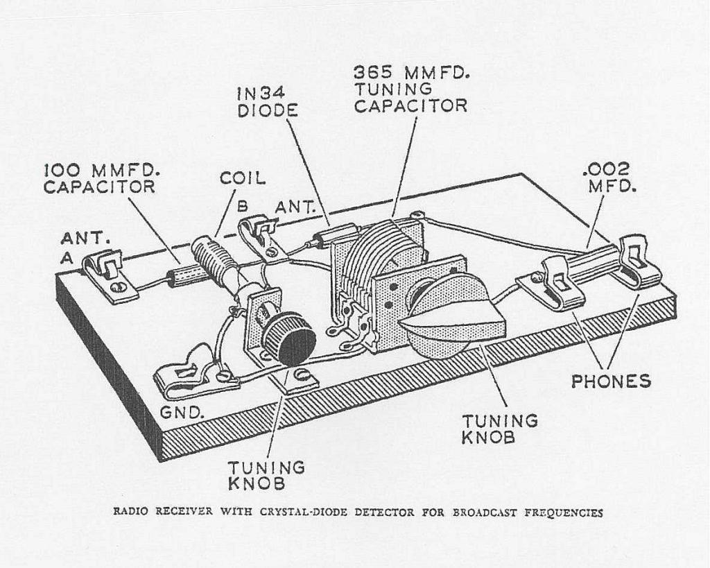 My actual interest in electronics has been there as long as I can remember. Since I was a kid (a little kid: like three or four) I had a fascination with electrical things – items ranging from extension cords to lamps: my parents thought I’d become an electrician. It started, I suppose, with Dad building simple flashlights consisting of a bulb and two ‘D’ cells taped to a yardstick. Other things I recall from my childhood include a Crystal Radio built from a design in ‘The Boys Third Book of Radio and Electronics’ which we got from the local library. I found a drawing Dad made of the actual radio he built on the back of an envelope with a cancellation date of 1969 (Dad typically drew lots of pictures on the back of envelopes) – it consisted of a piece of wood on which an open-vane tuning capacitor from an old tube radio, a 1N34 glass germanium diode from Radio Shack, and a hand-wound coil on a piece of wood dowel was assembled. Dad had also built a telephone system where he attached two telephones to a board – I don’t even recall if it worked (i.e. as an intercom) but it was a source of fascination nonetheless.
My parents fostered my interests and I even had my own workbench in the basement. From the age of six or seven and electronics was something we (my brother and I) were regularly exposed-to. Even around the home, we had a large (20″ tube) Admiral colour TV set (circa late 1960’s) which used over 30 tubes! When it konked-out, my brother and I would remove every tube in the set, take a shoebox full down to the local Towers store, and Mom would go shopping while we tested tubes for an hour (you could tell it was the 1970’s – a parent leaving two kids alone in a store for an hour !).
Testing tubes was a tedious affair: look-up the number on a large rotating chart, configure the machine for that tube using a series of rotary switches and potentiometers, plug-in the tube, press the button, and HOPE the meter read ‘BAD’ (in which case, problem solved). If the tube showed good, back it went into the shoebox and on to test the next tube. Eventually, you’d find a bad tube, the clerk would retrieve the replacement tube from under the machine.
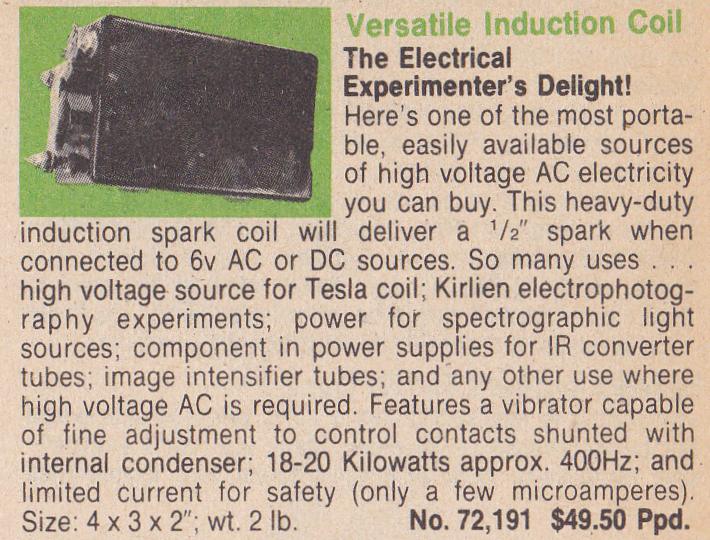 My parents fostered my interest in science and electronics, buying us some interesting things from Edmund Scientific including a hand cranked generator (a surplus unit used for army telephones) which, when cranked, could generate over 100 V to light a 60W bulb! A favourite, though, was a spark coil similar to that from a Model-T car (albeit a newer version with a plastic case). Dad soldered three large brass bolts onto the unit. When a 6V lantern battery powered the coil it produced sparks between two copper wires 1cm apart. The coil would easily light fluorescent tubes. I can’t count all of the experiments I did with that coil: everything from transmitting energy through the air by using two large tinfoil plates on the coil at one end (and a second set of plates some distance away with a neon lamp between them), sending high voltage through a trail of graphite filings between the two output terminals, lighting candles from the spark, to shocking my brother’s friends who sat in a prewired ‘electric chair’:). The output, although high voltage, was safe enough because the current was quite low – still, the jolt from the coil was quite startling!
… I did say ‘Sparking’ my interests …
And so, my interest in electronics, and science, was fostered and grew. I had torn apart countless old televisions and radios, keeping many of the parts for future projects, and we had accumulated a large box of vacuum tubes. Dad would also buy electronics magazines like ‘Elementary Electronics’ for us from Mickey’s cigar store on Main Street just down from his shoe store from which I learned about various circuits. Of course, a good part of my interest was started by observing my brother, Michael, who was into electronics at the time.
The late 70’s were a time when electronics, as a hobby, was the “in” thing and learning kits were common. My brother had one of those “1001” project kits in which you wired circuits between components on spring clips – everything from code oscillators to AM radio transmitters. It was a “MyKit 7” as I recall, from the old Consumer’s Distributing store, and it even had an Integrated Circuit. This was the funniest thing, though, since it was a THICK FILM circuit (not exactly what we’d consider an IC today). Components such as resistors and capacitors were fabricated using an applied-paste process onto the inch-square ceramic substrate. Even that was terribly unique since there were no real commercial products employing ICs yet (Computers, sure, but who had ever seen a computer close-up?) … a few years later and chips flooded the market with everything from logic ICs to the ubiquitous 555 timer. You still see electronics kits like this available occasionally, although they are nowadays a ‘specialty’ item (whereas in the 70’s they were available commonly).
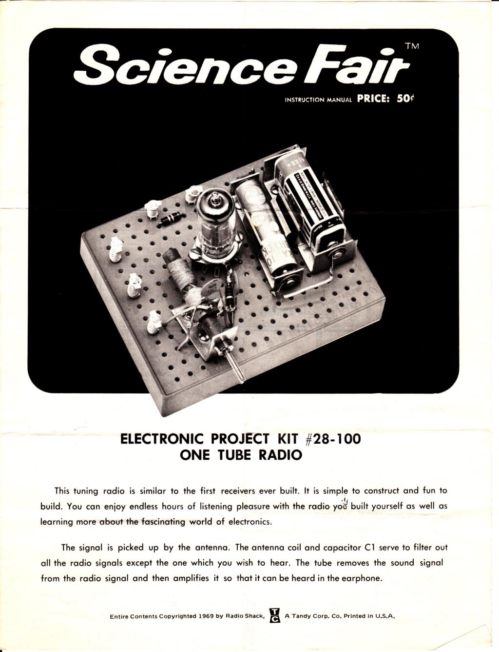 For Christmas, well, most kids would look through the wish book whereas I’d look through the Radio Shack Catalog. Take a look at RadioShackCatalogs.Com to see the kind of stuff they offered back then (That site, BTW, is incredible and if you were into electronics during the 1970’s it will surely bring back many memories). I’d frequently ask for either a “surprise kit” or a project kit like a P-Box Kit from Radio Shack. Each kit consisted of a red plastic box with a multitude of holes onto which the enclosed parts could be assembled to build a metronome, a radio, or, a night light. Some kits worked well (like the metronome and the night light) while others flopped (like the shortwave radio – never did have a knack for RF circuitry and even today “RF is voodoo”) but I learned a lot by building these including some basic transistor theory (like “apply voltage to the base and the device turns on” – I had no concept of current gain back then) and learning to read schematics, relating symbols to the actual component. One of my favorites was the One-tube radio kit which used a 1T4 tube and ran from a 22.5V battery (which fits into a C cell holder) and a AA cell for the filament. That one worked well as I remember and while I was totally solid-state centric (and dismissed people who, for example, said that tubes “sounded better than transistors”), I couldn’t help but be fascinated by tubes especially since I had seen so many tube circuits in old electronics magazines from the 1960’s. For those who loved these P-Box kits check out The P-Box Kits Page.
While it’s hard to find a good electronics surplus store these days (even in the seventies, electronics was already a ‘dying’ hobby), there were still a few stores like Olson Electronics in Buffalo, NY which supplied both surplus and new components. We’d buy a large (they sold it by the pound) surprise kit when we went “over the ditch” as we’d call it. Inside you’d find all kinds of junk including parts, motors, etc.! These provided a wealth of materials for projects.
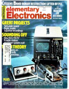 My favourite electronics magazine at the time was Elementary Electronics. Popular Electronics was good but the projects were too advanced for me at the time, and so EE had many simple projects that were easy to understand and learn how they worked (if not build them). Consider the Nov-Dec 1975 issue. Priced at $1.00, the main construction project of interest to me was a spaceflight computer (Project Spaceflight by Malcolm K. Smith). This analog computer project consisted of four utility boxes with a host of meters and switches (labelled, of course, with the requisite “DYMO” raised-plastic labels). The operator was required to “fly” the spacecraft by activating the rocket motor at appropriate intervals to keep it from crashing, all while watching the speed and height meters. This same simulation was popular in the late 70’s on early home computers. The actual circuit was two integrators (using 741 OP Amps). Switching the rocket motor on produces acceleration upwards while “gravity” accelerates the spacecraft downwards. Integrating acceleration produces a speed signal (displayed on an analog meter). Integrating again results in height, displayed on a second meter). The goal being to land the spacecraft gently (i.e. at near zero velocity) at the height of zero (i.e. when landing). I never did build that project, but reading through the article provided a description of how OP-Amps work (including how a split-supply worked) which would prove useful later when I started using these chips in various projects.
It was a timely article – the Apollo missions to the moon had just ended a few years earlier and the Space Shuttle was already announced – and so space flight was still an “in” thing. The author, BTW, was apparently quite a “Trekkie” since he makes many references to Star Trek episodes in the article (which even includes several photos from the series).
Another article I found useful in this issue was ‘An old flash from a new IC’ which featured circuits using what was at the time my favourite IC, the LM3909 flasher. Other notable features in this issue were a plethora of advertisements for CB’s (23 channel, of course, and one from Johnson for a CB featuring a very new LED meter display for signal strength), the required ad for Radio Shack P-Box kits (priced at $7.95 each and including both the one-tube radio and the night light), an Edmund Scientific ad, and a host of terribly cheesy classified ads in the back for everything from “Make $1000 a month stuffing envelopes” to “Beautiful girls wanting American men”. Long before the internet, you had to find spam yourself in the back of a magazine.
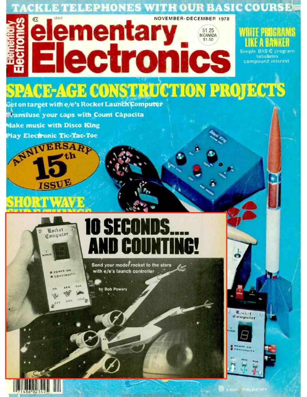 I built a number of project from magazines like Elementary Electronics – the cover of the 15th anniversary issue (Nov-Dec 1978) pictured to the right. Really, we (my brother and I) entered into the hobby of electronics near the end of the era … you just don’t find many electronics hobbyists who build projects anymore (nor electronics magazines for that matter). Perhaps electronics just became too complicated with the advent of SMT parts, micro-controllers (and the need to program them) and the necessity of circuit boards for high-speed circuits, or perhaps kids in the next generation just found other stuff like video games to occupy their time.
My brother reminded me that the Rocket Computer featured in this issue (which I included as an inset on the lower left of the scan) was one of my projects, not his, as he had trouble getting the counter to work. Indeed, I recall taking to IC’s readily although I also remember a lot of frustration over things like old CMOS chips which were excessively static sensitive and blew with dull regularity. I do remember using a surplus 7-segment display for the counter which came from a Radio Shack assortment kit of LED displays – Radio Shack had a lot of “assortment” packs available with quantities of LEDs, displays, IC’s, and other components like transistors. The transistors in one assortment pack were identified by a spot of coloured paint on each: four types were included (two NPN, two PNP types).
Click on the cover image to see a more detailed view … recognize the background? Very contemporary for 1978. Another project I had built was a touchswitch using a FET (from Radio Shack, of course). FET transistors were fairly new then (at least to most experimenters) so it was novel. A hand-shaped piece of boxboard covered with aluminum foil served as the touch plate which, when touched, caused an LED to light.
As well as Elementary Electronics (which provided a good start), I also regularly read Electronics Today International (commonly available in Canada) and later Popular Electronics (when my electronics skills improved).
Other projects I remember building?
How about a remote telephone ringer which used a neon light as an opto-isolator and rang a loud bell when the phone rang. Or a timer (555 based) which connected to a pocket calculator – you’d key in “1+1” and the circuit pressed “=” once per second causing the calculator to increment and count in seconds (This was a project from Elementary Electronics magazine, Sept-Oct 1976, entitled “Mark-time counter”). Or a guitar booster which was cloned from a commercial unit (a small single-transistor amplifier, basically). Or a full-blown synthesizer which featured modules like a VCO, sine-wave shaper, and ADSR. This large project consisted of a wood frame which held a number of modules built into aluminum panels. It was the size of a commercial keyboard.
Brain Candy: The Ontario Science Center
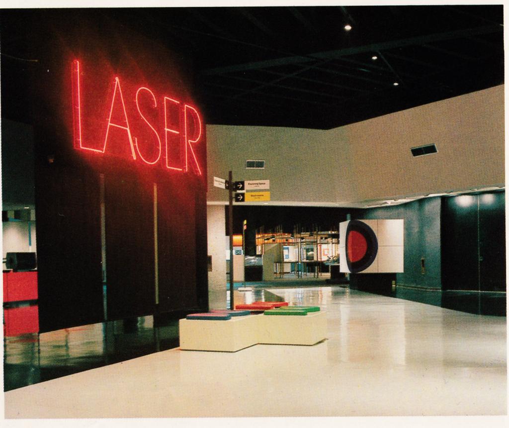 I suppose I can’t say enough about my parents and how they fostered my interests in science and electronics. They indulged my scientific curiosities, financed projects, and took my brother and I to the Ontario Science Center in Toronto at least once a year (A place I took my kids to when they were younger). The science center is an awesome facility featuring displays on a host of science topics ranging from astronomy to chemistry and up until the 90’s featured a demo on lasers. As a kid in the 70’s I recall well watching the display with awe! The center opened in late 1969 and was groundbreaking in that the displays were interactive and visitors were encouraged to push buttons. It was likely one of the first museums of its type.
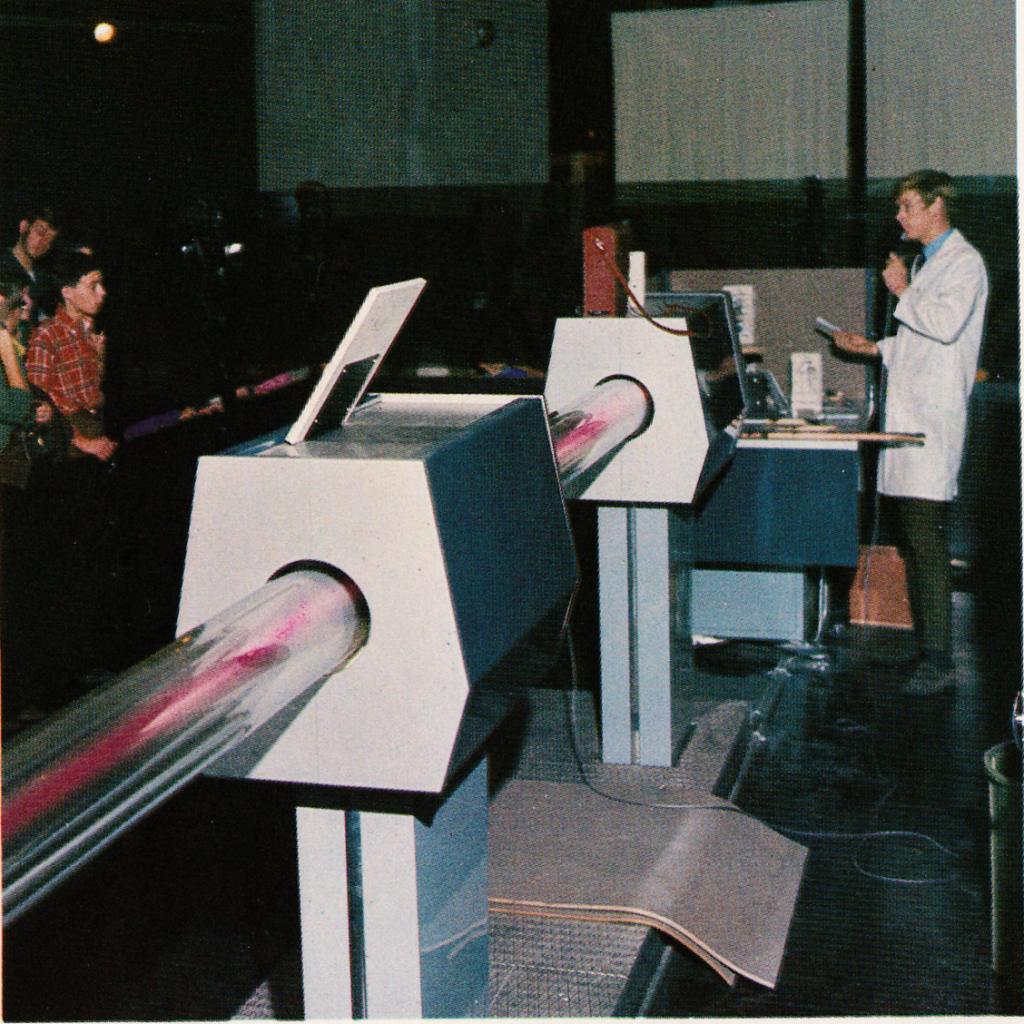 The focal point of the laser demo was a huge carbon-dioxide laser. Built for display on the third floor of the France pavilion at Expo ’67 in Montreal by the General Electric company of France, the laser found a home at the science center for the next thirty years until being retired. The laser was several metres long and had a rated power of about 100W. Demonstrators would evacuate the tube and then slowly leak helium (first), then nitrogen, and finally carbon-dioxide gas into the tube as fantastic colours appeared each time – you could see the gas travelling through the tube as the colour changed! After the last gas was added the laser began to lase and would burn a hole into whatever was in its path. My fascination with that beast (and it was a beast by today’s standards as a modern CO2 laser under a half-meter in length can produce the same power) as well as an argon laser they had there (with its vibrant blue, green, and violet beams split by a prism) sparked my interest in studying lasers.
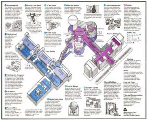
So, if I had to say one one place ‘turned my crank’ for science it would be the Science Center. The place has changed a lot in the past 50 years but it’s still a fun place (and YES, I still consider science FUN). For a view of what the place had in the hey-day of the 1970’s, click on the map for a larger version of the facility with highlights of all the demonstrations. The old laser display was removed reportedly because they could not afford to repair it any longer. The Electrical display, featuring a large Tesla coil, as well as the Chemistry display featuring liquid nitrogen are still there (although they have moved). And then there was the famed COFFEE machine!
This machine, which I likely monopolized during visits, simply said ‘COFFEE’ and was located in the center hall. The machine was built from discrete components and had a series of coils and capacitors for filters and oscillators. Lamps lit up the letters “C”, “O”, “FF” and “EE” as the machine spoke. Visitors could vary parameters using two analog pots to make the word sound different: bass/treble could be varied as well as the tone of the word from a “question” to an “exclamation”. Personal note: in the 1980’s I built a voice synthesizer based on a GI SPO-256 chip (Radio Shack actually sold these at one time). The first word it ever said: “coffee”.
Other really neat stuff I remember at the OSC which is now gone:
- The enormous tic-tac-toe game in the center of the main hall powered by a PDP-11 (probably an 11/45 with a full rack of switches and lights on the front panel). Back in the seventies, computers were all the rage and still somewhat new to the public (I mean, they sent you bills, but you could never really interact with one). Other exhibits in that same area included a logic gate demonstrator for AND and OR gates which used ping-pong balls to show how logic signals ‘flowed’ through these elements.
- In the mezzanine upstairs, the transportation display with a working model of canal locks in which a model ship ran up and down the locks. It even had a cool set of lights on a board just like real locks do (which control ship movement).
- In the lower area, the atom exhibit with a display of Rutherford’s Thorium decay experiment and the required small theatre showing the classic film ‘The Powers of Ten’ (you can find that film on YouTube nowadays: it is still worth watching).
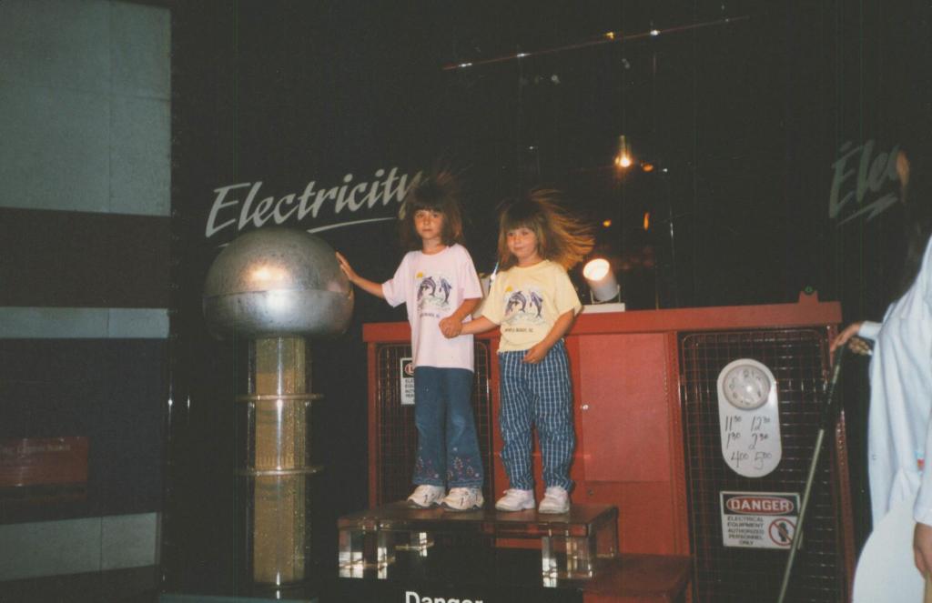 Of course I took my own kids there as well. Many of the exhibits I cherished were long gone but it was still fun. My kids are seen here in 2001 at the science center ‘playing’ with the Van De Graaff generator and having a hair-raising experience. Trivia: this photo was actually used on the cover of an album by the Danish group “Telstar Sound Drone” – look up the single “Mirror Pieces” on 7-inch vinyl (Bad Afro records, 2011).
Serious Electronics
As my learning of electronics progressed, I began to build my own circuits. I built a bunch of little circuits on the breadboard using chips like the 4017 decimal counter, the LM3914 bargraph display, and the LM3909 flasher IC: things like handheld games using LEDs.
By the age of twelve I was constructing multi-channel colour organs using SCRs and audio transformers. Most of the basic designs were found in books like ‘101 electronic projects’ which gave a schematic and a basic one-paragraph description … the ‘hobbyist’ approach to learning electronics (which I still believe is the best way to learn!). One of my favorite plans was a Single Channel Colour Organ. I expanded that basic design, with the help of an article in a 1967 Electronics Experimenter’s book (The “Musette” color organ by Don Lancaster originally in Popular Electronics July 1966), into a five-channel colour organ. Five audio transformers were used to drive five SCRs. R/C filter circuits on the secondaries were used to separate the frequencies for each channel – these proved to be the achilles heel of the design since they are sensitive to amplitude – and years later I would discover how active (OP-Amp) filters work which allowed vast improvement – and nowadays, when I built one again in 2010 for my daughter, I just threw a DSP chip at it and implemented the filters digitally. That design is outlined on this site on another page.
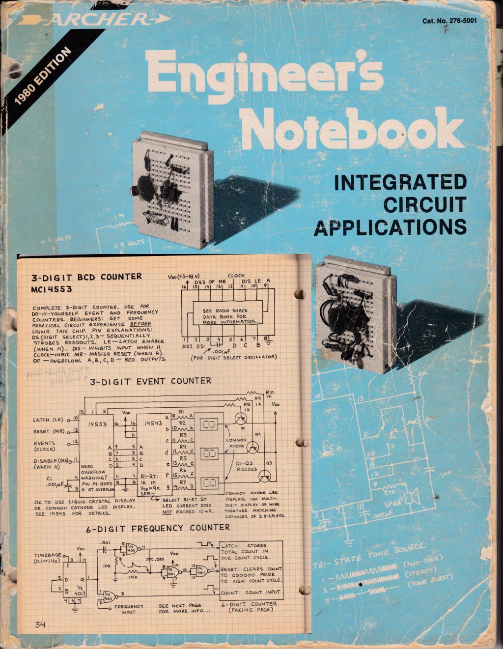 It is hard to imagine an engineer born before 1970 who does not have a copy of the Engineer’s Notebook by Forrest M. Mims III pictured here (my well-loved 1980 edition, with a typical page from the book shown in the inset). Radio Shack sold all of the components listed in the book – in the days before Digikey, and the internet, the only real place to get parts from readily was your neighbourhood Radio Shack which stocked chips, transistors, resistors and capacitors in their retail stores. One could purchase an SN76477 complex sound generator for $2.99 and wire it on a breadboard (also available at the store) to make all sorts of noises. Radio Shack’s chips all came with a data sheet stapled to the back to assist the builder – in the case of the SN76477 it was quite extensive and was the most complex chip many experimenters would have dared use – but even a pack of assorted SCRs came with a datasheet describing pinouts and application circuits. Other chips many experiments might remember are the LM3914 and LM3916 bargraph chips used to make 10-segment LED meters. I bet both of these chips ring a bell to many who cut their teeth into electronics during the late 70s and early 80s.
I took to digital readily – quite possibly because I lacked the theory to understand analog properly! When you’re self-taught in electronics by ‘the hobbyist approach’ you tend to focus on building things and not necessarily on how they work, yet to do analog justice you really need to understand circuit design, frequency response, have a decent ability to apply math, etc. Sure, I could design simple circuits and knew enough to put a large resistance in series to limit current to a device like an LED, but designing circuits like analog filters requires more complex math which I just didn’t have: at best I could build a filter from a schematic diagram and use a provided formula to calculate R and C values for a desired frequency response. For digital there was little theory to understand – apply 5 volts and the rest is simply ones and zeroes! The math was exceedingly simple (once binary was understood) and it either “worked” or it didn’t. Ahhh, a niche I fell into. Of course throughout the 70’s computers were becoming more common. Most were the ‘blinking light’ style with large impressive front panels like the PDP-11’s at the science center in Toronto that one could play ‘tic-tac-toe’ with. One local grocery store, Dominion as I recall, even went computerized with modern cash registers and a central computer (behind glass) complete, of course, with blinking lights. By grade 8 I had a my own computer, a REAL computer, an Ohio Scientific Superboard II. This glorious machine had 8K of RAM (expanded from the factory-standard 4K), stored programs on cassette tape, and displayed video on a TV as 24-column text (it is outlined on another page on this site). On the hardware side, I built I/O interfaces to drive LEDs and read switches (using gates line an 74LS30 for address decoders and 74LS273 octal latches for output) and my own 16K memory expansion using 2114 RAM chips (cloned, essentially, from Ohio Scientific schematics). On the software side, I learned to program BASIC (I specifically went with the Ohio Scientific machine as it had BASIC in ROM). I really ‘cut my teeth’ on that machine which was my first real hands-on intro to computers. My real interest in computers, though, lay with the hardware of the machine with software just an ‘evil necessity’ to make it all work (what was called ‘hardware hacking’ at the time) and in retrospect that was one of the biggest limitations to my progressing in computers – building serious hardware like a floppy drive interface or something using DMA really requires skill in programming in assembly language (you sure aren’t going to transfer data at 250Kbits/sec in BASIC!). I did, eventually, learn to program not just in BASIC but C and assembly language (on a variety of processors) but that came a lot later.
Although science was a fascinating subject, I spent most of my elementary school years learning electronics (by building projects) – electronics was a more accessible hobby and still “big” judging by the number of magazines on the subject in the 70’s and early 80’s. While in high school I took every electrical and electronics course they offered and began to learn proper circuit design (now that I understood things like transistor biasing). I also took every computer course offered to hone some programming skills.
I continued learning more complex electronics, especially digital circuitry, which I used in various science fair projects …
Adventures In Science – Science Fairs
My interest in “pure” science developed in parallel to my interest in electronics. I was always fascinated with optoelectronic devices making the bridge between the two subjects. Our family made annual trips to the CNE (Canadian National Exhibition) in Toronto and one stop was always at the Edmund Scientific booth. I’d always pick-up science trinkets, lenses, and prisms. As a (young) kid, I’d put a prism into the path of a sunbeam coming through the front window and marvel at the intense colours in the spectrum. It was little inspirations like this that drew me into the field of science, as well as those frequent trips to the science center.
I had dabbled into building odd science projects: I had attempted (with no design and almost no concept of the theory required) to build a carbon-dioxide laser from a Pringles chip can … oddly it did not work ;). Science looked like fun, but I didn’t really have the background at all.
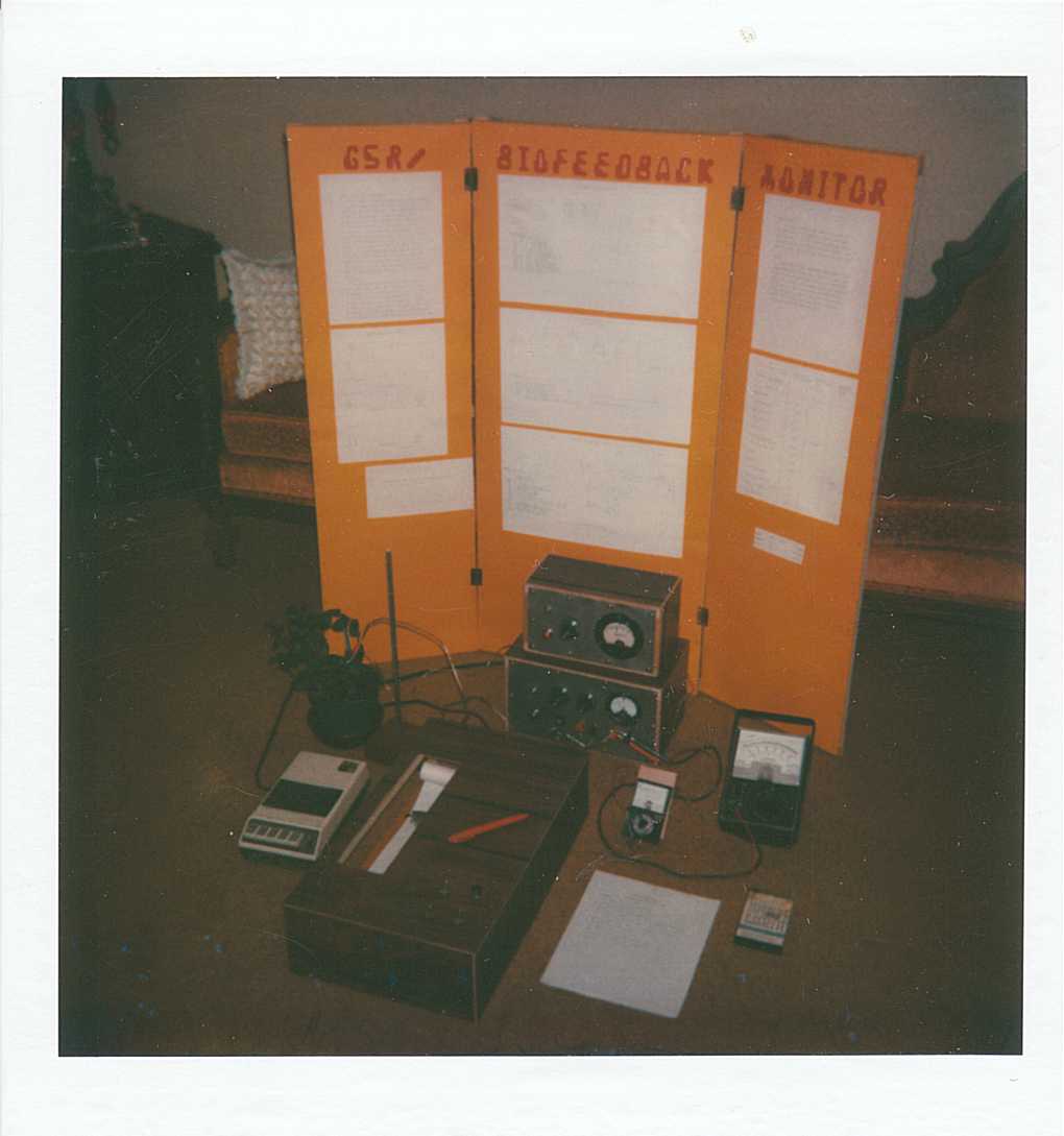
At the time, my brother had entered the local science fair, building a light communication system (the basic idea originating from an Elementary Electronics article in March/April 1976) and, following in his footsteps as all little brothers strive to do, I wanted to enter a science fair as well. I built a project for grade 7 entitled ‘A GSR monitor’. My (faulty) hypothesis attempted to prove that plants had nerves: It was a completely ‘build and show’ project with little science behind it. The project wasn’t spectacular but it was a start and involved some interesting electronics like a homebuilt strip-chart recorder. The basic unit itself was nothing more than a homebuilt power supply and a sensitive microammeter in series. Most parts came from a load of old electronics provided by a cousin in Buffalo, NY, who was disposing of a garage-full of old parts and books (electronics and ham radio). On a visit there, my parents picked-up a load of books and parts including things like indicator lamps – those nice little coloured jewels so popular in the 50’s and 60’s – and like any techie I incorporated lots of indicator lamps in my projects. The most interesting part was the strip-chart recorder that used a transistor to amplify the signals from the GSR monitor and cause a pen to move when the current exceeded a preset value.
Where did I ever come up with the idea of a GSR monitor ? Long before the internet the primary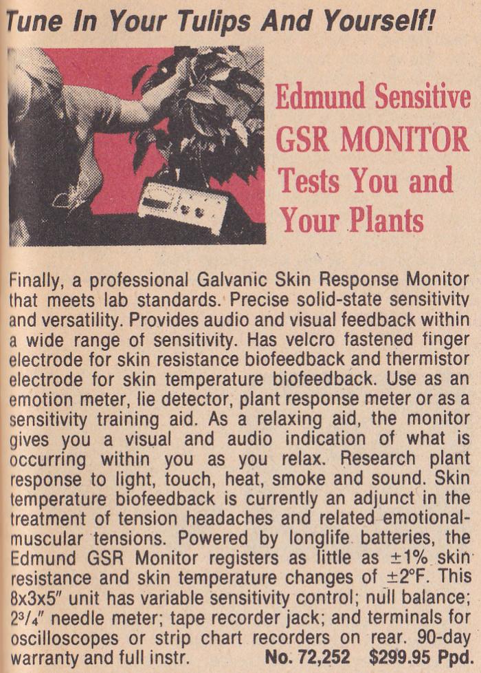 source of ideas for projects were magazines and catalogs. The Edmund Scientific catalog, in particular, provided a lot of ideas since many of the products were geared to the ‘hot topics’ (some being ‘pseudoscience’) which in 1977 included biofeedback, Kirlian photography, and GSR. Remember, this was the 70’s, just after the drug-tainted 60’s. Disco was IN, Psychedelic was IN, even mirror balls were IN (Yes, I found them in that catalog as well!). Could you tell this was the 70’s from the caption ‘Tune in to your tulips’?
And the many colour organs I built? – they were big in the 70’s as well and Edmund sold many types of units. Numerous electronics magazines featured construction articles for colour organs as well.
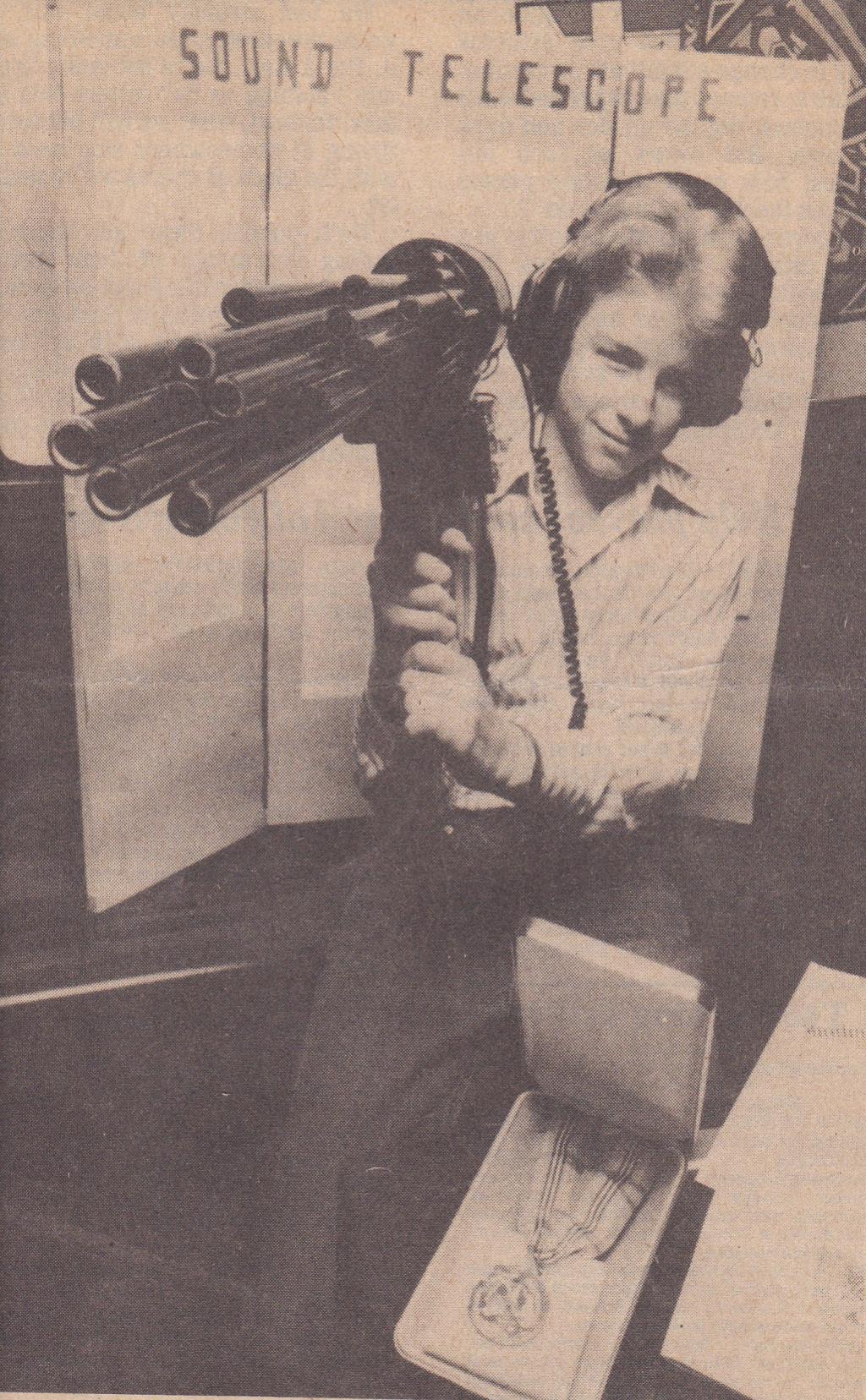
Grade eight and I needed (OK, Wanted) another project. In the back of an electronics magazine I found an ad for plans (the company was ‘Information Unlimited’ as I recall) for a number of interesting devices including a small Tesla coil and a ‘Sound Telescope’. Dad ordered both sets of plans and the sound telescope looked quite neat – picture a series of tubes, each resonant at different sound frequencies, with a sensitive amplifier and headphones. Mounted on a shoulder-mount (and looking a bit like a rocket launcher) we built it from a load of CPVC plastic tubes (the white, rigid type used for water, at a cost of $30 for all the tubes). A microphone from Olson electronics picked-up the sound which was fed to an amplifier scavenged from an old portable reel-to-reel tape recorder (bought at a garage sale for a few dollars) and was made even more sensitive by adding a homebuilt preamplifier between the the microphone and the amplifier (using one transistor – a design I used for a “linear power booster” for my guitar which served as a preamp). I built the amplifiers into a small plastic box from Radio Shack and powered it from two 9V batteries. The machine worked, and was amazingly directional. It won a few small awards at the fair including an honourable mention from the Youth Science Foundation and a bronze medal award from the US Army which was usually reserved for senior students (I was, apparently, the first junior ever to receive it). The science was certainly better (at least there was a tangible principle here) and winning an award, especially a bronze medal, certainly encouraged me to continue. (That bronze medal is still among my most cherished awards). Photo Credit: The Evening Tribune, May 5, 1980.
For me, science fairs provided the best outlet for my creativity in science and for many years occupied the majority of my time.
One of my biggest limitations was access to information. Unlike today, where the internet has led to drastic changes in the way information is available, I was restricted to a large degree to magazines (electronics was a popular hobby back then so there were a number of periodicals available), the public library (where I had to manually search through old Scientific American articles from the stacks), catalogs (great for ideas), and old magazines like a 1968 copy of ‘Science Experimenter’ which featured a host of neat projects (a Tesla coils, a Van De Graaff generator), almost all geared to science fair projects. With electronics still a popular hobby there were, at least, a number of decent electronics and surplus stores within a few hours drive. As a kid, one of our favourite shops was Olson electronics in Buffalo where we’d always pick-up a surprise pack of assorted electronic items for dirt cheap (they sold it by the pound). Later, Active Surplus in Toronto became a favourite.
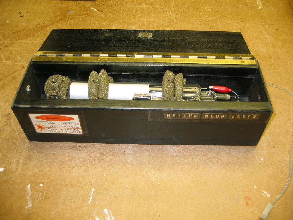
When I was in grade eight my parents bought me my first real laser: this was a real game changer! Indeed, I was fascinated by lasers since I’d seen them at the Science Center but to actually own one was almost unthinkable, and here was one available and almost affordable! The laser, purchased from Arkon Electronics (on Queen St. in Toronto and long since out of business) was a soft-sealed glass HeNe tube and a power supply kit consisting of a bag of parts and a photocopied schematic. The kit was simply listed in their advertisement in Electronics Today magazine as “HENE Laser Kit $149.95” (That seemed like an awfully large sum of money back then, but I sooooo wanted one – owning a laser was like owning one’s own interstellar spacecraft 😉 ) . I built the laser in a day, the power supply on a piece of perfboard, and Dad built a wooden box to house the tube. I used the laser for countless experiments in the two years it lasted before gassing-out (Old laser tubes, being soft-sealed, had particularly short lives). The night I got it working I was already experimenting with mirrors and making a laser light show – all to the tune ‘Another One Bites the Dust’ as I recall: funny the odd things you remember 😉 – it was probably a first attempt to build a laser show like I’d seen at the CNE in Toronto (it was an attraction on the midway – laser light shows were all the rage in the 70’s and into the 80’s). This new ‘toy’ was fascinating and it was amazing what happened when you put things like ornamental plastic in front: interference patterns galore! It is seen here in the wooden box, the tube was mounted in three ‘cradles’ lined with foam. The output aperture was a modified RCA audio connector with the center terminal removed – mating fiber optics could be made cheaply with RCA plugs. A teacher provided me with a piece of fiber optics to experiment with.
In grade nine I used this laser to build a light communications system for a science fair project in the local Niagara Regional Science and Engineering Fair. A transformer was inserted into the ground lead of the HeNe tube to impress an AC voltage on top of the DC current flowing to modulate the laser’s intensity, the beam could then be transmitted through free-space or a fiber optic to a receiver using an FPT-100 phototransistor.
That project won me a trip to the Canada Wide Science Fair (CWSF) in Waterloo, Ontario (where I later studied). The project started as a laser-light show and ended-up as a full-fledged communications system. The trip to the CWSF was important to me personally as it showed me how to do research and allowed me to network with others. At that fair I recall meeting one guy who built a number of homebuilt lasers (he showed me several good sources of information including the Amateur Scientist column in Scientific American), as well as another who built a really neat robotics project (it resembled R2D2 of Star Wars fame). I got a taste of dorm life, had tours of labs at the University (which included seeing a massive argon laser), and had fun in general (they had PET computers at the dorms to play games, and a room full of the latest video games including ‘Elevator Action’ for which I built a MAME machine years later).
I present below the abstract for the project scanned from a typewritten (yes, word processors were rare in 1980) page I found in my parent’s attic in 2002:
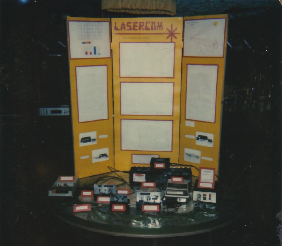
The first Lasercom system was built for a demonstration in an “open house” night at my school. This is when I decided to use it as my science fair project. First, the laser had to be modulated. The idea for modulation was obtained from an old Popular Science magazine which described a foolproof burglar alarm system. It was hard to foil because it used 60 Hz modulated light source (He/Ne laser) instead of the usual plain red light beam, thus a flashlight cannot be used to “fool” the alarm system.
The article suggested the power line to the laser tube be cut and a small filament transformer be inserted in the circuit. A 60 Hz tone from the power lines is extracted by another transformer and the tone output was fed to the other modulation transformer. It was thought that if a 60 Hz tone can be impressed on the beam then a varying frequency signal could also be used. This method was tested and was found to work quite well.In the first prototype system, the audio signal from a radio was fed to the modulation input on the laser. The beam was split in two parts by a piece of glass. The weaker beam was fed to a silicon phototransistor and to the input of an amplifier. The more powerful beam was reflected off a mirror and then off a second vibrating mirror which was connected to a speaker coil driven by the output of the amplifier. The mirror vibrated in step with the signal, thus the reflected beam also vibrated,making a small laser light show and also demonstrating the principles of light communications.
 Two basic ideas came from books. The first was the modulated HeNe laser which I saw in an old Popular Science magazine (That approach was similar to the one used in the Elementary Electronics magazine article in which impressed voltage from a series transformer was used to modulate the bias current of an LED). The second was the light show which used a simple mirror bouncing on a membrane stretched across a speaker. Care to guess where that idea came from? Edmund Scientific’s catalog, of course. My project was really just putting it all together: The modulated laser to send the audio signal, a photodetector and amplifier (modified cassette recorder) to receive it, and a speaker with a mirror to deflect the beam. There was some decent science in that project and unlike earlier ‘build and show’ projects, I was now putting-together concepts on my own. The modulation of the high-voltage, for example, was the taking of a basic idea and expanding on that idea … the very nature of science itself (i.e. building on known concepts). This was required for any decent project.
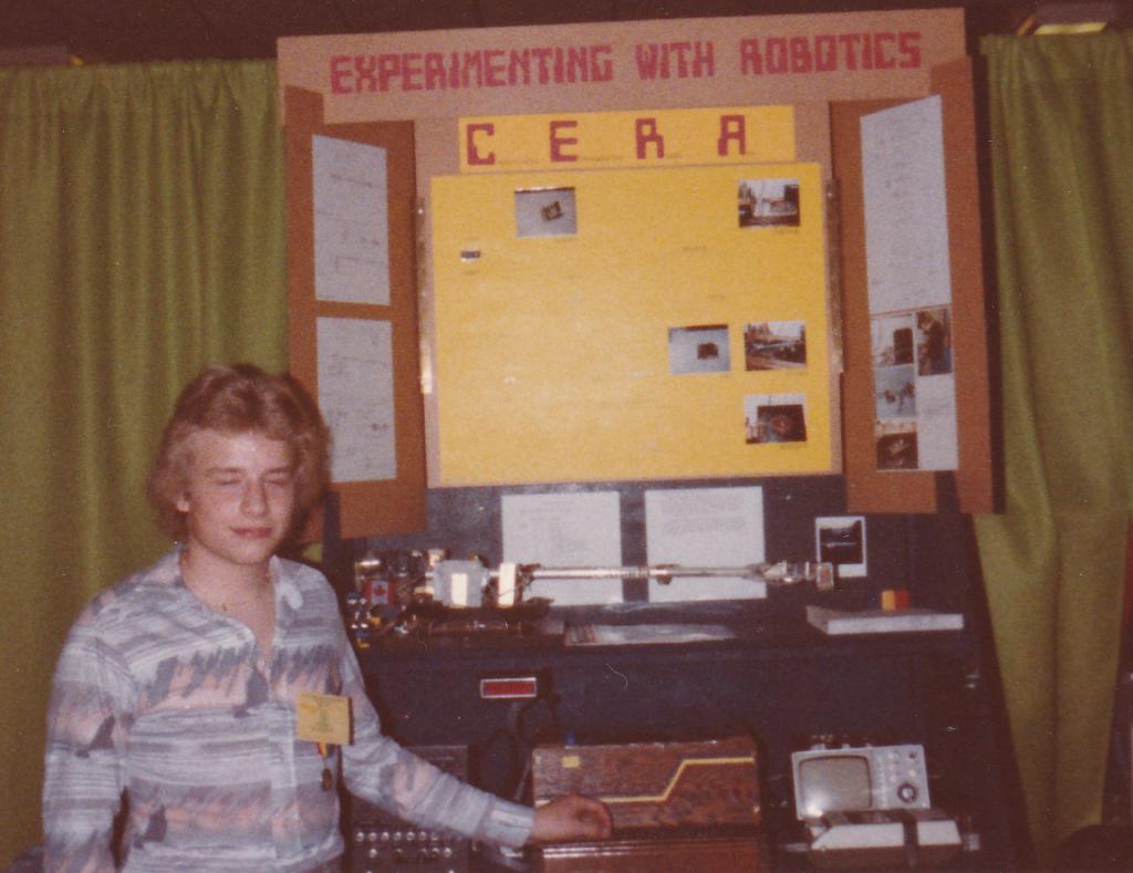
By grade ten, I would have loved to have done a laser project but my HeNe laser was dead (it lasted only two years before the soft-sealed tube gassed-out) and besides, I was now fascinated by robotics having seen a neat robot at the CWSF in Waterloo the past year. I decided to use my Ohio Scientific computer to control a robotic arm (robotic arms were all the rage – Canada just contributed the arm to the space shuttle). I learned about interfacing (address and data buses, decoders, clocks, and all that jazz) and had my computer control a basic arm which was completely homebuilt. The robot is seen here on top of the display with the controller (with a panel of LEDs indicating I/O status) behind my arm. The computer, a single-board 6502 machine with integral keyboard that ran BASIC, was packaged in a homebuilt plywood case which held the computer, power supply, and the I/O circuitry built on 44-pin cards. The small TV to the right of the computer served as a monitor (which was large enough, given that the display resolution was only 24-characters by 24-characters: in those days 1K of video memory was pretty standard).
That engineering project garnered a trip to the International Science and Engineering Fair (ISEF) in Houston, Texas. I did not place at the ISEF but again, the experience was incredible for I was able to see what is required to make an ‘International’ grade project – while it was a good engineering project it demonstrated nothing new or novel. I noted that the projects that _did_ win had certain characteristics and all used references from scientific journals like ‘Applied Physics’. I had to get my hands on those and was told to check the local University library as they often have these collections available to the public. Brock, our local University library, stocks numerous physics journals which served as an invaluable source for ideas. The ISEF just overwhelmed me – the projects were awesome (almost all of the photos I had taken were of other projects), the venue was huge (the Astrohall in Houston), students from around the world (Japan, China, Sweden, England, etc) were there … it was a great place to exchange ideas. I was also turned-on to science, more-so than engineering at this point in my life.
I was still intrigued by lasers and wanted to construct a working laser ‘from scratch’. My fave? The argon. Having seen these at the Ontario Science Center as well as at a few laser light shows I was in awe at the vibrant green and blue beams. Soooooo …. I set out to build one. Gathering a load of information on the laser I decided a pulsed laser was the only practical way to do it (the gain is high, the average power dissipation is low). I learned basic glassblowing and using soda-lime tubing (which can be worked with a low-temperature propane torch) built a basic laser tube. It took me a week of experimenting with glass to learn _how_ to glassblow well enough to make that tube. The tube used electrodes from a spectrum tube (bought new from a science supply house and cannibalized almost immediately) and the ends of the glass tube were carefully sawed at Brewster’s angle. Quartz pieces (compliments of the glassblower at our local Brock University) were used for tube windows and epoxied on. For a vacuum system all I had available was an old Cenco single stage vacuum pump (compliments of the high school) and I purchased a lecture bottle of high-purity argon (along with the glass tubing, both from Sargent-Welch scientific). Again, my parents supported my science ‘habit’ and forked-over the $275.69 for parts. I ordered the parts in July for the science fair next March! Indeed, this project (and the ones which followed) involved major investments of time and effort – I now knew that was required for an “International” caliber project.
Well, constructing a gas laser, especially a low-gain one like an argon, on a piece of 2-by-4 lumber is begging for disaster and the laser never really ran as a laser. I could not afford proper (i.e. concave with a dielectric coating) mirrors and so a first-surface enhanced-aluminum telescope mirror was used with the hopes that the pulsed gain of the blue argon line would overcome losses in the laser. This was probably the biggest problem with the design: had I thought harder (and done some calculations using the gain threshold formula, which I did not yet understand), I’d have made the laser longer since a 2m long pulsed argon would likely have exhibited over 30% gain and would have oscillated despite large losses at the mirrors (Even then, though, the vacuum system would have been problematic as I found out dozens of years later when I repumped an old argon laser for an experiment at the college). Mind you, the project was by no means a loss as I learned an ENORMOUS amount about vacuum systems, high voltage work, and other techniques I’d need now and in the future. Still, what to do with the argon laser in which I’d now invested precious time (started in July, completed by December) and (my parents’) money? The answer was in an journal article (in the Journal of Applied Physics, Vol 48, No 3, pp. 1385) concerning the ‘plasma pinch’ effect in which a high current through a gas plasma generates a magnetic field which ‘pinches’ the plasma causing current to be reduced after which the plasma expands and current increases: the plasma current hence oscillates. By this time I was begging Mom to drive me to the local University library and leave me there for the afternoon. I spent hours in that place, bringing along with pockets of change for the copier.
I needed a decent oscilloscope (which I borrowed from Mr. Zavitz who serviced electronics and was also an Ohio Scientific computer enthusiast, hence how I met him) and an open-shutter 35mm camera (I had just gotten into photography and bought my first 35mm camera, a Praktica EE3, from Consumer’s Distributing) to record the oscillations occurring in the discharge: this all seems so primitive today – now I simply plug a USB key directly into my scope and capture it. Current was monitored with a Rogowski coil (a small transformer) in series with the discharge (small enough that its inductance did not affect the discharge much). Photos of a single (dim) trace on the oscilloscope screen were captured by the 35mm camera with an open shutter and the output was traced onto a piece of translucent drafting film placed on to of the original photo. The observed traces showed an 8.25 MHz oscillation on the upper-edge of a low-pressure discharge at 88.2A.
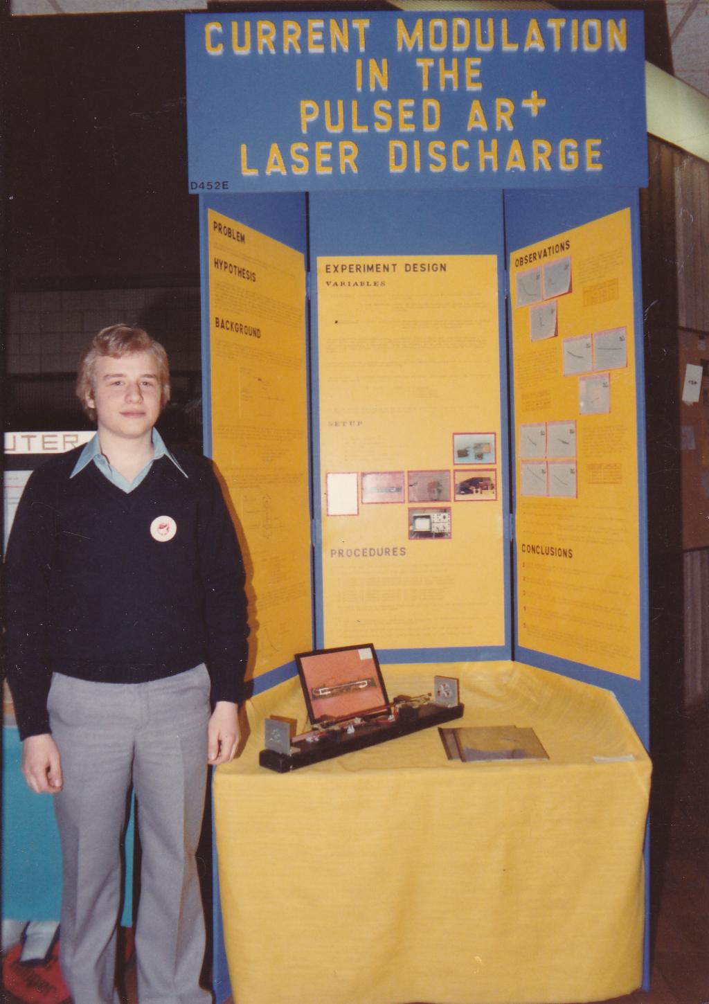
In grade 11 I entered that project, which also featured a presentation board of ‘International’ caliber (it was freestanding and about eight feet tall and all lettering was stenciled by hand in a large-font). Unlike previous projects, I did not even attempt to display a working setup of any kind, instead showing photos of the working model – far too many projects attempt to ‘wow’ judges with an impressive device (‘build and show’) but miss the underlying science – I had learned a few important lessons from my previous trip to ISEF. It did extremely well at the local fair winning a trip to the International Science and Engineering Fair (ISEF) in Albuquerque, NM that year. I present the abstract for that project below:
CURRENT MODULATION IN THE PULSED ARGON-ION LASER DISCHARGE
This is an investigation of the phenomenon, factors affecting, and the causes of current modulation in the pulsed argon-ion laser discharge. If the amplitude of the modulation varies inversely as tube pressure and occurs only at high discharge currents, it may prove that the modulation is caused by the plasma pinch effect. The pinch effect, which may be responsible for the modulation during the main part of the current pulse, is calculated to occur at discharge currents of 30A or greater. The modulation occurred only when employing the 1 uF discharge capacitor and only at the upper and mid-trailing edges of the current pulse. The amplitude of the modulation was varied to a greater degree at the lower-trailing edge than at the upper-trailing edge. In addition, modulation frequency increased at the lower-trailing edge of the current pulse. The data suggests that the modulation does occur in the laser discharge, varies inversely as tube pressure and occurs only at high discharge currents. As large currents are needed to cause the modulation, these findings seem to indicate that a cycle of plasma pinch and destruction of the pinch is responsible for the modulation. Since the frequency of the modulation is lower at the upper-trailing edge of the current pulse, it seems that ion-acoustic waves are present as a cause of the modulation during the early part of the pulse.
First Award – Optical Society of America
Third Award – General Motors ISEF
It placed third overall in the ISEF (quite respectable) in the physics category. Aside from placing, the trip itself was just spectacular! I have fond memories of that trip – it was my favourite science fair trip of all time – and have many memories of the trip including touring Sandia Peak and the city of Santa Fe, Los Alamos Laboratories (and the huge linear accelerator there), and enjoying a Laserium laser light show (Laser Floyd) which was brought-in especially for the event.
At the fair in NM, I met James G. Small from MIT. At the time I recall saying something dumb like ‘you wrote the article in the Amateur Scientist on the dye laser’? Close … he wrote the article on the nitrogen laser, now famous with almost all laser enthusiasts! We talked for over an hour and essentially designed my _next_ year’s project. I’d tried to build a nitrogen before, but did it all wrong using thick copper plates and dielectrics. He put me on the right path and for that I was grateful! In the bowels of Active Surplus in Toronto I found the required thin PC board (0.015″ thick) from which the laser was built. I used that single-stage vacuum pump to evacuate the tube and rented a Q tank of nitrogen on my brother’s account at the local welding gas supplier (he had an oxy-acetylene welder and so had an account with them for tanks). I borrowed his oxygen regulator which, with an adapter, regulated the flow of nitrogen into the laser. After a few blown PC boards, the laser was at last a success producing a powerful UV beam, and I was on my way to building a dye laser for experiments.
The Scientific American Amateur Scientist article written by Small (June 1974) describing the construction of a simple nitrogen gas laser which outputs in the ultraviolet was, of course, the inspiration for the construction of my nitrogen pump laser. I didn’t make much light (pardon the pun) of the nitrogen laser in the project since it wasn’t the focus of the experiment.
A prototype dye laser was built on a piece of 1-by-6 wood. UV radiation from the nitrogen pump laser enters through a cylindrical lens (mounted on a focusing tube from an old microscope) and onto a cell containing Rhodamine-6G dye solution, the dye purchased from Sargent-Welch (it was not ‘laser grade’ dye but worked fine given the enormous gain it exhibited). A flat, aluminized HR and an OC made from a beamsplitter served as the cavity. This proved that it could indeed be done and despite the simple construction, worked extremely well producing a bright yellow beam.

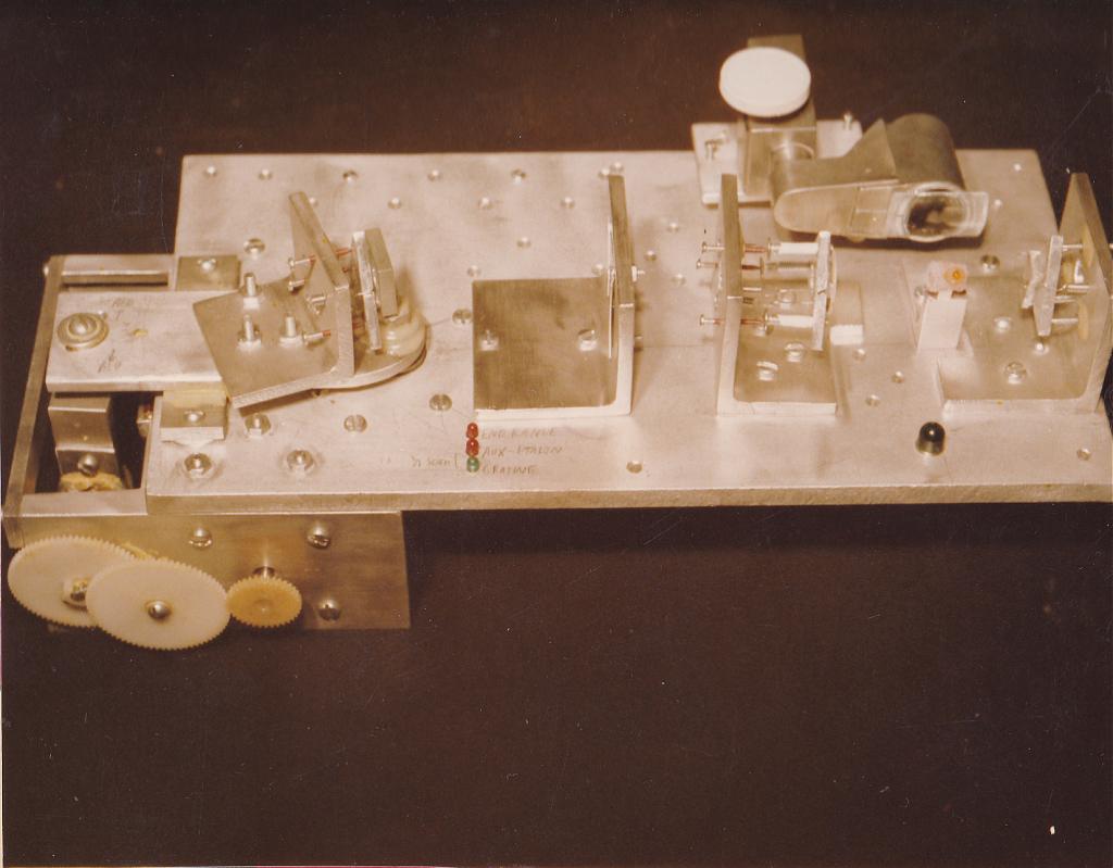
The actual laser used in the experiment (above right) was much more stable: it was built on a 3/4″ thick piece of aluminum with aluminum mounts for all optics, a precision rotating stage using multiple bearings for a diffraction grating used to select the output wavelength, and space was provided between the dye cell and the grating for additional collimating and wavelength-selecting optics. The main point of the experiment was to use an inexpensive dielectric filter as an intra-cavity etalon to reduce the linewidth of the laser output (normally quite broad given that dye amplifiers have large gain bandwidths).
The project required constructing not only the nitrogen pump laser as well as the dye laser but also a spectrograph to record results (such as the spectral bandwidth of the laser output). This used film to record the spectrum – since I was into photography at the time and had a basic darkroom I developed and contact-printed negatives. This was done with black & white film. For the project display, I used colour film to show the results (which were quite dramatic as a dye like Rhodamine-6G can be tuned through a range from yellow-green to red and 7-diethylamino-4-methyl coumarin can be tuned through the blue and green portion of the spectrum). This helped make the display board more impressive and truly re-enforced the nature of the tunable laser and the huge range of wavelengths the output could span.
The abstract describing that project from the 35th ISEF:
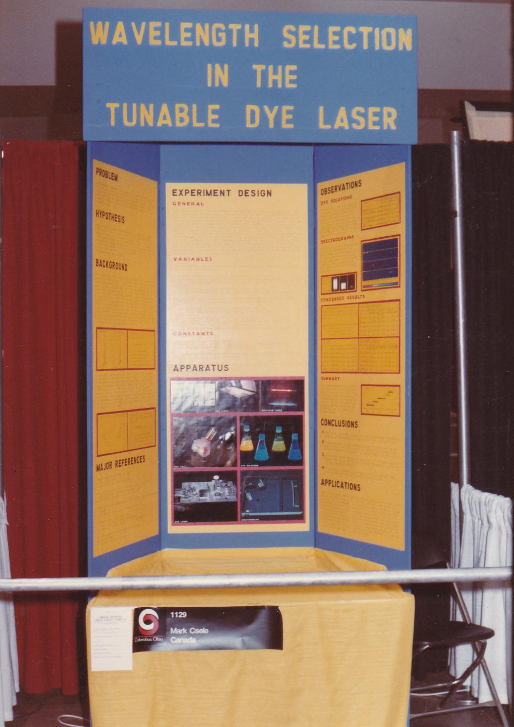
WAVELENGTH SELECTION IN THE TUNABLE DYE LASER
The experiment presented will investigate the factors affecting the spectral characteristics of a nitrogen laser pumped tunable dye laser. The wavelength selection system is unique as it uses a medium resolution diffraction grating instead of a high dispersion type usually found in this type of laser, thus a grating used alone as a wavelength selector should yield high spectral widths of the laser output. The use of intra-cavity wavelength limiters -an optical slit or filter- should reduce the spectral width to approx. one nanometer. Rhodamine 6G; 7 diethyl amino, 4 methyl coumarin; sodium fluorescein; a mixture of the two preceding dyes; and 4 methyl umbelliferone were employed as the organic lasing dyes. Ethanol was found to produce the strongest and most stable lases. Tested concentrations varied between 5 x 10⁻⁵ m/l and 1 x 10⁻² m/l. Using a 600 line/mm diffraction grating alone, spectral widths of approx. 6 nm were produced. The use of an intra-cavity optical slit between the dye cell and grating reduced the spectral width by one-half, while the use of a dielectric filter (As a Fabry-Perot interferometer) reduced the spectral width to 1.2 nm. Using five dye solutions, a continuous wavelength range from 602 nm to 392 nm can be covered. Since the wavelength range is so broad, the laser may be useful as a spectrographic emission source; however, a high dispersion grating must be used to obtain low spectral widths. Data obtained on the use of a slit or filter can be applied to a laser employing such a grating.
First Award – American Association of Physics Teachers
First Award – General Motors ISEF
First Award – United States Air Force
Honorable Mention – Optical Society of America
This project was the apex of my science fair project experience. Many large (8×10) photos dominate the display to show the equipment used (since there was no demonstration of it working). My 1984 science fair project placed first prize in the physics category in the 35th International Science and Engineering Fair (ISEF) held in Columbus, Ohio that year.
There was real science in there: like my grade 9 project I took a common element (dielectric filters) and applied it in a novel manner. Where many lasers used an expensive etalon to reduce spectral width, this one used an inexpensive dielectric filter. And unlike my previous project where I lacked the mathematical knowledge to fully describe and predict the effect I was seeing, I researched this one thoroughly and understood the ins and outs of dielectric filters and gratings!
Winning first award was a huge honour, but perhaps the best prize of all was the USAF award which included a week-long trip to tour US Air Force R&D facilities in Maryland (Andrews), Ohio (Wright-Patterson), Tennessee (Arnold), Texas (Brooks), and Florida (Patrick) each designed to show the range of cutting-edge research carried out by the Air Force – I was the only non-US citizen to have won such an award. It was inspiring, to say the least!
In the course of researching this project I had photocopied almost every laser article in the Amateur Scientist columns. As well, I used a good number of scientific journals for information: Applied Physics, Applied Physics Letters, and the like. I spent a good deal of time in the library at Brock University researching (this was, of course, long before the web and so information on amateur laser construction was much more difficult to come-by. I learned a lot about the mechanisms of gain and loss in a laser as well as laser optics (although with the large gain exhibited by the dye amplifier inexpensive, and lossy, optics could be used).
Finally, in grade 13 (in Ontario, at the time, high school was five years), I entered a two-year project entitled “Wavelength Selection in Tunable Dye Lasers”.
The project was essentially a comparison of the spectral characteristics of the nitrogen-laser pumped dye laser (1984’s project) to that of a new flashlamp-pumped laser. The new addition was built around a capacitor obtained from a surplus defibrillator purchased from a surplus store in Buffalo, NY.
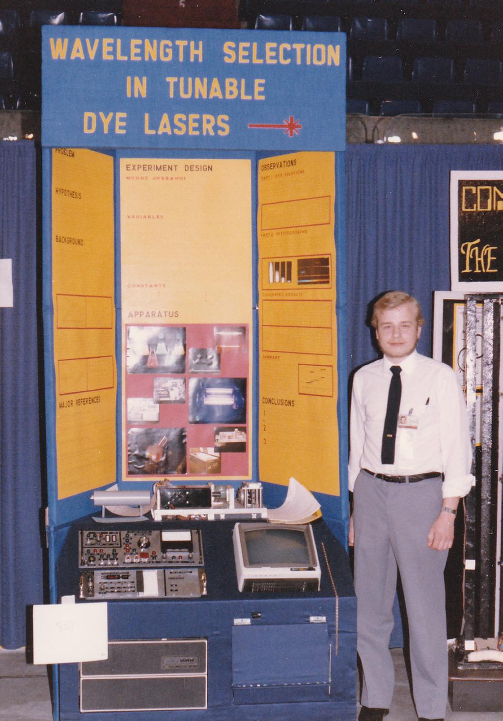
A close-up of the project itself shows the flashlamp-pumped laser on top and the computer-control underneath. The computer, my old Ohio Scientific 6502-based system, was built into a PDP-8/A case as seen here. The laser was configured as a spectroscopic light source – the computer controlled a step-motor which tuned the laser through the entire range. The laser was fired at intervals, and the transmission through the sample recorded. Beside the monitor and the keyboard are the controllers: the top panel controls the laser itself (charging of the capacitor and firing the flashlamp) and the lower panel the interface between the computer and grating drive.
The project was more engineering than science and the flashlamp-pumped laser lacked a totally unique element (unlike the nitrogen-laser pumped dye laser) – frankly, it was a matter of biting off too much. I should probably have concentrated on the optical elements of the laser instead of the computer-control system as I did (it was fun building the electronics, but that isn’t science) and while I made a point of showing-off the entire control system (and went back, somewhat foolishly, to a ‘build and show’ project), that isn’t what ‘gets points’ at a science fair. Regardless, I won the local fair and it was suggested that I go to the CWSF (in Cornwall that year) rather than the ISEF since the project was very similar to the previous year’s entry (it incorporated half of the previous year’s project). I placed second at the CWSF that year.
Off To School
Having spent most of my high school years building science fair projects I was leaning towards science (as opposed to engineering) and studied physics (first, at least). I enrolled at the University of Waterloo in the (four year) honours science program. University was actually a bit anti-climactic, at least the academic part: I was no longer ‘the smartest guy in class’ nor was I busy indulging in science which _I_ found interesting rather I was studying whatever was in the curriculum and in many cases, getting buried in school work. I made some huge mistakes: like underestimating what it took to really understand calculus (sure, I went through the motions in high school but I did not ‘get it’ which resulted in a failure and subsequent re-taking of a first-year calculus class). In second year I became discouraged with physics and changed my major, then changed it back (taking a summer term to make-up for lost time so I’d still be able to graduate in four years – this also meant five straight terms of school). These were all lessons in life: lessons about sticking-to-it and that you eventually have to ‘pay the price’ (which in my case meant truly learning and understanding math). Suffice it to say I was educated schooled not only academically but about life in general!
School was comfortable enough, at least. I lived off-campus for first year then on-campus at the Village-1 dorms. My room featured a PC, a stereo, fridge, microwave oven (which as disguised as a filing cabinet since cooking appliances were forbidden) and, for one very hot summer term, an air conditioner carefully ducted through the window to exhaust hot air. In retrospect, the air conditioner contributed greatly to my success that hot summer since I was more than happy to stay in my cool room and study calculus, which is what I was there for in the first place (well, not solely for calculus, although mastering it was the biggest challenge for me). Of course, it was not an “allowed” item, especially since it blew breakers when other students in adjoining rooms tried to use a hair dryer – the addition of a simple timer to shut it down before everyone else awoke solved that problem (leaving me only to explain why each morning I had to dump a pail of extremely cold water into the sink).
… and despite school, I still had time to learn some neat stuff …
During my days at Waterloo I dabbled with a few interesting things like high voltage, made frequent trips to the surplus store in Waterloo, bought a ton of surplus at University surplus sales once a year, built a three-channel colour organ for nostalgia’s sake, and made an interesting little transmitter to hijack FM stations replacing their signal with my signal (which usually involved offensive music like einsturzende neubauten).
Periodically, my friends and I would make trips to Toronto, occasionally to visit the science center and occasionally to shop the surplus stores on Queen Street invariably followed by dinner at the Old Spaghetti Factory …. always a treat! At the surplus stores we’d buy a whole bunch of computer parts, cheap, and use them for various microprocessor projects. I remember purchasing old PC boards full of 256K DRAM memory chips and desoldering them with a propane torch so I could use them in my PC.
Well, you meet some really strange interesting people in the dorm like one curious soul, Kenn Heinrich, who built a large Tesla coil in his dorm room. Kenn’s coil consisted of two neon-sign transformers (15,000 volts each) driving a metre tall coil wound on black ABS pipe. In its peak of operation, it produced arcs 26 inches long! That corresponds to approximately a half a MEGAVOLT! (You don’t measure voltages that high with a DMM after all). Numerous improvements (e.g. a low inductance spark gap) and numerous mishaps (e.g. starting carpet on fire when the side of one transformer exploded violently) led to the final version which caused a big enough stir at the dorms to have the Ontario Hydro safety inspector pay Kenn a visit! Needless to say that pretty much curtailed development before he hit the ‘holy grail’ of One Megavolt.
Aside from helping in the development of those Tesla coils (I had learned a lot about fast discharge circuits from my days of building lasers for science fair projects which was useful here), I built myself a Marx-bank generator in my dorm with the original application envisioned as an excitation source for a pulsed neon laser. The device produced about 200kV but with a risetime in the nanoseconds – the Fourier transform is quite broadband so it kills almost all forms of communications. The generator was built from pieces of ABS sewer pipe used as coaxial capacitors with spark gaps fabricated into plumbing tees between the caps. That generator threatened my new PC more than once (I had already had to rebuild the output drivers on my CGA card a few times due to a flaky monitor and wasn’t looking forward to diagnosing yet more problems) so it was shelved before it cost too much time in repairs of adjoining equipment … in a ten-foot square dorm room there isn’t much space to escape a rogue high-voltage arc that follows some odd, unpredictable, path!
Of course building Tesla coils and such required trips to surplus stores on the hunt for parts. On one fated trip I tortured my friends with an hour and a half of (early) Kate Bush music on cassette only to find the surplus store in London, Ontario, playing the same music when we got there.
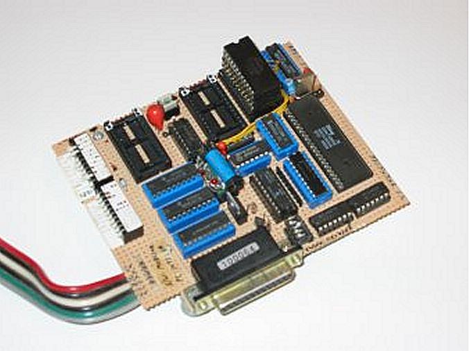 Aside from high voltage experiments I also learned about microprocessors and microcontrollers and built my own Z-8 based EPROM programmer to further my hobby in computers. Until then, I had built numerous interfaces and memory expansions to my old Ohio Scientific computer but had never actually built a microprocessor system “from scratch”. In those days, EPROMs were a necessity and few people had a programmer – I was introduced to the Z8-BASIC chip (Z8671) as used in a Byte magazine article and built an EPROM programmer of my own design using this chip, wire-wrapping it on a piece of perfboard. A bank of DIP switches configured the socket for various types of EPROMs (the unit was originally designed for 2K-Byte 2716 and 4K 2732 types but was expanded many times to accommodate multiple types as larger chips became available on the surplus market). These switches configured the function of various pins (e.g. pin 21 is Vpp on a 2716 but A11 on a 2732 ) as well as voltages (Vcc and Vpp), the rest was done in software written in BASIC (the only language I knew at the time, except perhaps FORTRAN). To use the programmer the main program was first uploaded from a PC using Kermit to the unit then data was uploaded/downloaded to the chip in the same manner – the BASIC interpreter on the chip acted as a bootstrap allowing the program to be uploaded (otherwise it, too, would need an EPROM just to start). A stack of 2K (6116 compatible) RAM chips with the chip-enable lines bent upward and wired to a 74LS138 decoder provided 8K memory for the system (2K chips were all that was available cheaply from surplus suppliers at the time).
They say school “teaches you to learn” and that it did. The art of learning is one all students must master and included many late nights studying including, in my final year, the occasional “study party” in the physics building where a bunch of us got together to attempt to decipher what the prof covered. At these parties, attended by twelve or so students, we’d get together and try to solve problems from class. We’d collect $2 from everyone, run out to the closest convenience store to buy chips and Coke, and spend hours poring over complex problems. When someone got it right, we’d all examine _how_ to solve the problem properly. All part of the learning process!
In my final year of physics I had decided I should have gone engineering. The job prospects for a physics grad just weren’t what I wanted to do in life: one of the realities of the day was that many of the science jobs were for a “lab rat” which didn’t appeal to me and unless you were willing to commit another four to six years to physics you’d never get to do serious research (and even then, I met a number of post-docs who didn’t even have stable positions yet). I finished my degree in physics, of course (I’d already invested three years of my life, what’s one more?) and then went on to take a few more years of avoiding reality … errr … learning in order to complete a degree in computer engineering at McMaster University. Having a physics background, this degree was fairly painless (I had already mastered calculus … nothing else could possibly be that challenging). I finally learned to program properly (I had already started learning assembly code on my own for the Z80 but C was a part of the curriculum) and learned a lot about computer systems: everything from operating systems to computer architecture. In my spare time I built a few microprocessor-based projects using a Z-80 and was finally able to do more complex things with a computer. Developing a program in assembly code, back then, meant crash-and-burn development cycles: write an assembly program, burn it into an EPROM, put the EPROM into the target system, watch it crash, revise the program … a slow an tedious process. For my thesis project I built a complete network system using Z-80 CPUs with an SCC chip to implement a 1Mbps RS-485 link – that project embodied a lot of neat technology (I was now using advanced stuff like interrupts and DMA) as well as a lot of concepts I had learned in school (the whole networking thing and how arbitration works).
… and then real-life set-in somewhere along the way (mortgage, job, marriage, kids, cat … I hear a country song in there somewhere). Still being an ‘Amateur Scientist’ at heart, I have constructed several lasers since those science-fair days. And since my computer engineering days I migrated to embedded controllers. More on that in the next section …
A New Chapter … Quite Literally
Well, by 1992 I had accomplished my educational goals: still not sure if I should become a scientist or an engineer, I had done both. It was finally time to get a real job. I was hired by CP Rail System in Toronto as a system specialist which was, for the most part, programming multi-threaded control systems for real trains. It was a cool job (I have always liked trains and here was a chance to work with a real railway), and I learned a LOT not only technically but also about the way business works. I did a lot of C programming there as well as some REXX (which was used for install scripts – that seemed to impress the senior members of the team more than anything).
I still built microprocessor-based projects in my spare time: one of my first since leaving school was a caller-name display system that logged callers and used a database to display a name via an RS-485 network using the yellow/black wires on the building telephone system. This project used a Z-80 as the main processor and Z-8’s (with an ISR written in assembly) for display units. I also built a new EPROM programmer (since micros back then still needed EPROMs for code), this time using a PC front-end (written in C) and driven from the parallel port of the PC (this was very pre-USB). I was looking into the new ‘PIC’ series from Microchip as well but back then it was an EPROM-based device with a window and so not much improved from what I was already using (and it, too, needed a special programmer).
We had our first child and I wasn’t around much – given the commute was 3-4 hours a day I left before she was up and got back after she was asleep: Either I was going to find a job closer to home or we were going to move closer to my job.
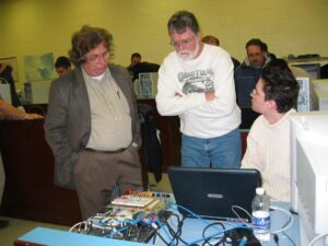 I had honestly thought about teaching one day, but I didn’t see it coming as soon as it did so two years out of school and I landed a position as a professor of Computer Engineering Technology at Niagara College. I was hired to teach, primarily, hardware courses (which was perfect) so I nicely fit in, teaching interface electronics (82xx chips on an ISA bus- students actually built their own interface boards) as well as embedded systems. I adopted the PIC series from Microchip, then just a small company, but the RISC architecture lent itself well to learning as it presented students with a simple model for a processor and the code was equally simple to follow. At first, we used windowed EPROM-based devices with ‘crash and burn’ development but EEPROM and Flash quickly replaced that and made code development soooo much easier! Eventually, each student was provided with an In-Circuit Debugger.
I did that (computer engineering technology) for about seven years at the college. My “big thing” there was a final term course (CTEC1630) in which students used an embedded processor to design and build a complete system – anything from a computerized drum kit to a talking Furby controlled via a windows app. In the photo here, two of my colleagues (long since retired themselves) look-over a student project at the end-of-term demonstration.
In addition to using embedded controllers for teaching, I did engineering work on the side (moonlighting) building three-phase industrial power control systems. I also built a number of projects around the house including a Hallowe’en costume for my kid which had a PIC to allow LEDs on her ‘butterfly wings’ to twinkle.
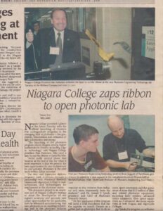
Enter the launch of the Photonics programs at Niagara College in 2001 and I found myself full-circle: I was back to where I started in physics and better yet, making a career out of the one topic I truly loved: lasers. I taught numerous courses on lasers at the technician, technology, and at the applied-bachelor level. The article to the left, from the Evening Tribune (Oct 3, 2001) shows the grand opening of the program in which our college president Dan Patterson used my baby flashlamp-pumped YAG laser to cut a ribbon and open the lab (there’s a story behind that laser, too, as I rebuilt it from an old CW arc-lamp pumped YAG laser that was given to me DOA. I used it for classroom demos in my technology & society class for years).
So I moved (sideways) into the new photonics department where we (the faculty) built labs at the college for the new program. Creation of these new laboratories required the construction and rebuilding of many lasers and laser systems, many still gas lasers in the early 2000’s. We built a high-powered laser lab populated with a number of new and used lasers including three large-frame argon-ion lasers (including a 5W Coherent Innova-90 and a 20W Innova-200, a few smaller air-cooled argon and kryptons, several carbon-dioxide lasers including an MPB DC laser and several Synrad RF lasers, a Lumonics 600 excimer, a Coherent tunable Ti:Sapphire laser, two YAGs (one a brand-new 20W Lee LDP-20 DPSS and one a flashlamp-pumped Quantel 660), and a host of other smaller lasers. It was a bit of a dream come true. As well as lasers, my other forte is high-vacuum and thin-film technologies. We built a Mass, Optical, and Infrared Specroscopy lab at the college which featured two turbomolecular pumping systems for reprocessing gas lasers (HeNe, Ar, Kr, etc) and for mass spectroscopy work. We also had a full class-1000 cleanroom for production of thin-film devices – this lab was originally designed for our microelectronics program in which we taught chip-building.
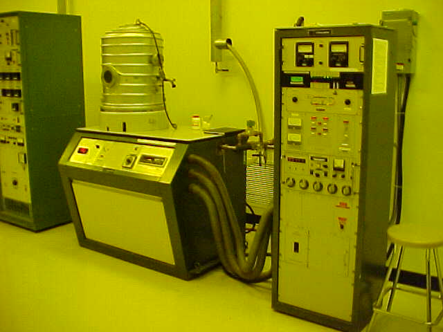
Pre-photonics-program, I taught a thin-film course for the microelectronics program (I was ‘loaned’ to them) as I had a background in it from my studies in physics (I did a thin-film lab at Waterloo). Our deposition facility started with an old single-source Edwards system for aluminizing silicon wafers which I expanded to use multiple sources and include a quartz microbalance: I actually had students do an optical filter lab in which they deposited a three-layer MDM filter (since one could actually ‘see’ the results) and, believe it or not, calculate the frequency change of the crystal to determine the film thickness. Labs were designed to give students practical experience at using equipment to make real devices although one of the first ‘real’ labs in the photonics thin-film course was having students deposit a film onto sunglasses so they had a cool mirror-finish which changed colour as the angle of incidence changed – students loved that lab.
We expanded the lab once photonics really got going to include an in-house built multi-source diffusion-pump based thermal system with a real deposition monitor (which finally replaced that old Edwards system), a sputtering system (a Lesker PVD-75 with both RF and DC generators), and eventually a cryopumped six target eBeam system. So while originally hired at the college to teach computer engineering technology, my teaching load migrated almost entirely to photonics courses (which was just as well as the management decided to cancel the immensely successful three-year computer engineering technology program in the mid 2000s despite it having decent enrollment and almost 100% employment … I never got over that).
Thin-film and vacuum technology (PHTN1432) was a staple subject for me. That course was lab-intensive with students completing labs on gas discharges (primarily operation of a high-vacuum system), mass spectroscopy (analyzing various gas samples), gas laser repumping (incorporating skills from the last two labs to make a HeNe laser work), thin-film deposition (depositing films using a thermal deposition system to make simple structures like MDM filters), and fabrication of thin-film optical devices (e.g. advanced coatings and dielectric mirrors using a cryopumped eBeam system with ‘hard’ materials such as MgF2 and even ZrO2).
The thing I really enjoyed was building lab equipment. Aside from building lasers and laser setups for various labs I had the opportunity to build some neat setups for my students including a HeNe repump experiment, and an argon laser experiment in which students pumped-down a laser tube, removed impurities (monitored by an RGA on the system), and filled it with lasing gas. The HeNe repump experiment is still in use (at least it was in 2023) – it consists of a commercial Melles-Griot HeNe tube with a filling stem welded to the original tube and connected to a turbomolecular pumping system using an Edwards EXT-series pump (capable of pressures lower than 10-6 torr) and equipped with two Baratron gauges and the RGA. In this experiment students experience how to remove impurities using multiple flushes of pure helium and electron bombardment, and the effect of residual impurity gases (in ppm) on the output of the laser. “Barbie pink” I always told them was the colour of the discharge when you got it right, but most students preferred the more scientific way using the mass spectrometer to determine the correct He:Ne ratio for the tube!
This experiment, as well as the argon experiment, are both outlined on my homebuilt lasers page in more detail.
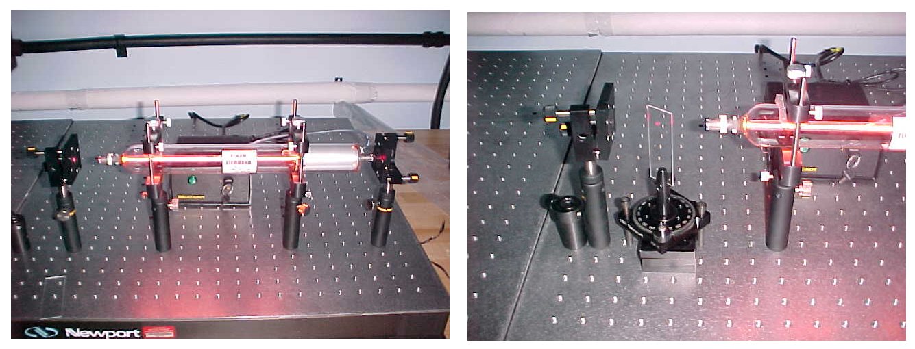
Aside from thin-film, lasers were my thing. I taught laser fundamentals (the actual physics of the laser) in the third term and practical details of various laser mechanisms in the fourth term. The third term course (PHTN1300 in the two-year technician program) included basic labs such as determining Planck’s constant plus a rather involved lab in which students align the optics and determine the gain of a Melles-Griot WPR-252 laser in which the laser amplifier tube has two windows and optics (both OC and HR) are separate. This was a three-week lab and often it took students a week just to get the hang of alignment (done both with an autocollimator and the ‘rock & bump’ methods). Once the laser was working, students would insert a glass slide into the cavity to act as a loss. By summing all losses in the cavity, the gain of the amplifier could be determined. This lab gave some important skills as well as the ability to see some of the mathematical concepts become useful! The helium-neon laser was used extensively as a vehicle in this course to demonstrate a host of concepts as it was a ‘textbook’ laser, obeying most of the rules.
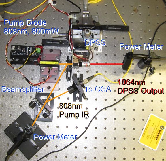
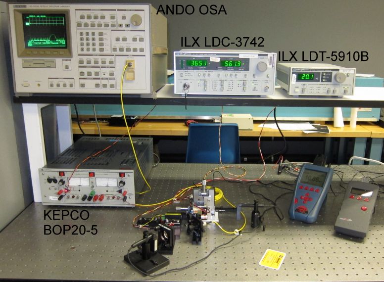
The fourth term course introduced students to concepts such as Q-switching, second-harmonic production, behaviour of laser diodes, and others. The actual lab equipment was built in-house. One of my favourite labs was the DPSS lab, seen to the right. In this lab, an 800mW laser diode pumped a 1064nm Nd:YVO4 DPSS laser . The temperature of both the pump diode and the DPSS amplifier were controlled by TECs. Optical power and the spectrum of the 808nm pump laser was monitored as well as the output of the DPSS at 1064nm.
Students could vary the temperature of the pump diode and observe the effects on pump wavelength (and ultimately the absorption of pump radiation which shows-up as output power of the DPSS) – that is a big deal with DPSS lasers. Temperature of the vanadate amplifier could also be changed which allowed students to see the effects of re-absorption loss (which isn’t bad at 1064nm but is much worse at 946nm – that was a different lab). The take-aways from this lab were (i) how critical it was to control the temperature of a pump laser diode so that the output spectrum matches the absorption spectrum of the DPSS amplifier material and (ii) how cooling a solid-state laser amplifier reduces re-absorption loss ultimately leading to higher output powers.
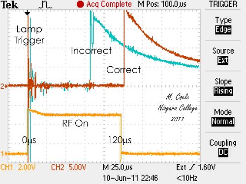
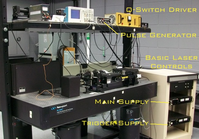
Another key lab from the fourth term was the Q-Switching lab. This lab was inspired from a few grads who worked for large laser manufacturers and spent a good deal of their time aligning Q-switches for industrial lasers – this lab was designed to give students experience at this alignment procedure.
The lab setup consisted of an old, modified Control Laser CL-5 laser (the same one used to cut the ribbon to open the program) pumped by a flashlamp (scavenged from an old Honeywell Strobonar photoflash bought at a garage sale years ago) and fitted with an AOM Q-switch (taken from a similar old Nd:YAG laser from an old resistor trimmer). Aside from varying parameters such as timing, a large part of the lab was spent aligning the AOM so that Q-Switching occurred properly (a skill which is trickier than is sounds). After that, the gain of the laser was determined by using an inserted loss such that the loss of the (now aligned) Q-Switch in the “off” position could be determined … a decently-aligned switch could deflect well over 70% of intra-cavity radiation and so induce a large loss which prevents oscillation. So aside from the skills learned in the lab, there was some math involved in calculating losses and gain.
I developed many labs during the over twenty years of teaching photonics – at first many were centric on gas lasers (e.g. the argon laser which was still popular in the early 2000’s) and then migrating towards solid-state lasers. Early labs included diagnosing ion laser power supplies, double-pulse lasers (setting-up the timing and EOM oltages on an Apollo double-pulse ruby), laser alignment and modes (using an MPB IN-200 CO2 laser and a Pyrocam beam profiler in which students aligned the 3m cavity), laser scanning (in which students programmed their own laser light show which used two GS scanners), laser-pumped lasers (similar to the DPSS lab above but using a tunable Ti:Saph laser pumped by a 20W Coherent Innova-200 argon), TEA lasers (we had a large Lumonics TEA-203 CO2 laser), Excimer lasers … many of these labs came and went as we updated the curriculum, and sometimes because a laser failed (which we couldn’t afford to repair) or we acquired a new laser (like an Ultrafast Spectra-Physics Tsunami). Yes, sometimes the labs were determined by the availability of equipment as some of this stuff was ghastly expensive!
Here’s a few links to lab videos I made in 2020 when we were teaching remotely during CoVid – they later served as pre-lab videos:
- Gas Laser Optics 1 detailing alignment of the optics of a HeNe laser
- Gas Laser Optics 2 detailing measurement of gain using a HeNe laser with separate optics
- HeNe Tube Reprocessing a favourite lab in which a HeNe tube is evacuated and filled with a working gas mix
- Bendix Thermal Evaporator a basic diffusion-pumped system used to make multilayer devices
- E-Beam Evaporator an advanced cryopumped system which made excellent hard coatings
- E-Beam Evaporator (Part 2) detailing actual evaporation procedures
During the course of teaching photonics, I wrote two texts on the subject: Fundamentals of Light Sources and Lasers (Wiley, 2004) and Laser Modeling (CRC, 2014). These were aimed at courses I taught in the second and third years of the program.
So, teaching in photonics, I had come full-circle and back into the field in which I started. I even went full-circle with the science fair which inspired me so many years ago becoming judge-in-chief for the Niagara Regional fair for eight years (until it was time, too, to let someone new take the reins as we re-start the fair in earnest after the pandemic).
But after 29 years of teaching it was finally time to call it a day and move on. And so, the next chapter of my life begins …