With our trailers getting heavier, and us getting older, it has become quite the feat of strength to move a 7000lb+ trailer around the yard, necessitated by the fact that we have to push it through a 9 foot opening to get to the rear of our yard where it is stored. Presented is a motorized trailer dolly which can literally “turn on a dime” allowing easy ins and outs from the yard.
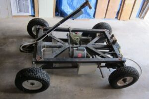 This unit was built primarily from parts scavenged from my father-in-law who, years ago, built a dolly to move his fifth-wheel trailer around his yard. The original dolly was built onto an ATV cart (purchased from Princess Auto) and featured a tall tower for the fifth-wheel pin (removed in this photo). It was a large beast almost four feet across by six feet in length made of 2″ square steel tubing, salvaged here for this unit. Essentially all parts of the new unit were salvaged from the original dolly including the tires, shafts, motor, and gear reducer.
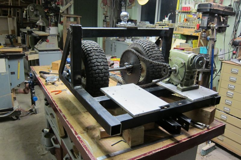
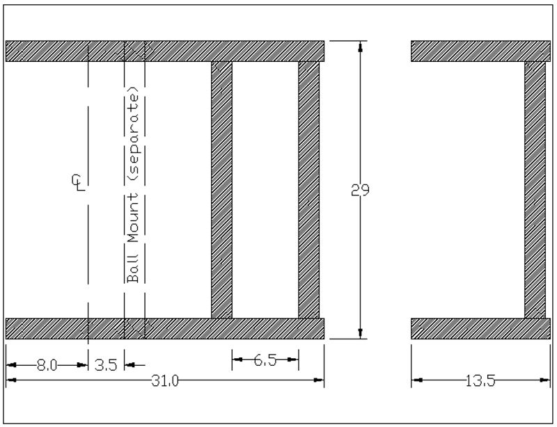
The main frame of the dolly is constructed of 2″ square steel tubing. The sides of the unit are 31″ in length and two cross-members 25″ in length are welded across these, 6.5″ apart, making a 29″ wide unit. The basic design of this unit has the tires mounted far enough apart to allow the electric tongue jack to operate freely – many designs examined featured a support across the front prohibiting use of the trailer’s own jack.
The main shaft was then assembled for a “test fit” before proceeding to complete the welding of the ball mount on top, this consists of a 29″ long piece of 1″ keyed shaft material. Two 16×6.50-8 2pr turf tires were welded onto hubs with keyways. The original cart tires were free-wheeling onto the shafts so weldable hubs, of the same type used to make the sprockets and with 1″ keyed holes in the centres, were welded onto the tire rims one on each side and with the keys aligned so a single piece of keyway could be used to lock both hubs onto the shaft. To begin, only one tire is to be locked onto the shaft as a drive tire however the option exists to insert a keyway into the second tire for dual-wheel drive if required. Each tire was then slipped onto the 1″ main keyed shaft along with an 11″ drive sprocket (the sprocket was a type “50×54″ meaning 54 teeth, a #50 standard chain (5/8″), and a hub required). Normally, you’d just purchase a 1″ keyed hub and weld it onto the 11″ sprocket however my used sprocket already featured a 3/4″ hub. Using a 1″ silver&deming drill the hole in the hub was enlarged to 1″ to slip onto the shaft then the entire sprocket coupled to an adjacent smaller sprocket with a 1″ hub via four grade-8 3/8″ bolts (which were then welded for extra security). Finally, the shaft is supported by two 1” pillow-block bearings at the ends of the shaft.
The entire shaft assembly was then placed onto the side arms of the frame and the location of the bearings marked. Half-inch holes were then drilled into the side-arms of the frame to hold the bearings using a drill press. It is necessary to drill these holes for the main shaft bearings before the rest of the welding (which then obscures the holes). The shaft was then removed.
One could argue that for optimal strength the entire shaft including the bearings should be placed under the frame however this would have made it impossible to mount the gear reducer and motor – made difficult by the fact the oil filled reducer must sit upright when mounted. The pillow blocks have a load rating of over 1000 lb each, though, so this is likely not a concern.
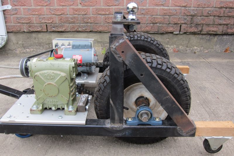
On top of the frame, another piece of 2″ tubing was welded at right angles to carry the 2 5/16″ ball above the tires. The top of the 2″ tubing was mounted 20″ above ground with the tires installed. An upside-down “U” of tubing was pre-welded (29″ across, like the frame, and with the top part of the tube 13″ from the frame) and welded at a location where it will still allow the bearings to be mounted (the holes previously drilled allow locating these bearings). The tubing was welded on all four sides. Angle-iron was then used to brace the upright tubing, welded at approximately 45 degrees between the side-arms of the frame and the top support. The room under the braces was used to mount the bearings for the main shaft.
On top of the 2″ frame a very heavy 1/2″ thick piece of steel was used to hold the ball. Lacking a welder large enough to handle this thick steel, three large bolts (Two half-inch and one 3/4″) were used to secure it to the frame. A 1″ hole in the thick steel plate allows the ball to be bolted onto the unit. The ball is placed about 1″ forward (i.e. towards the motor side) of the main shaft so that the tires will take the majority of the load.
The shaft was now assembled and bolted onto the frame. Several “stops” were added (discs with an allen-key to lock them to the shaft) which prevents the shaft from moving left/right and to lock the position of the “free” wheel (which, as mentioned, could be converted to a drive wheel if later required).
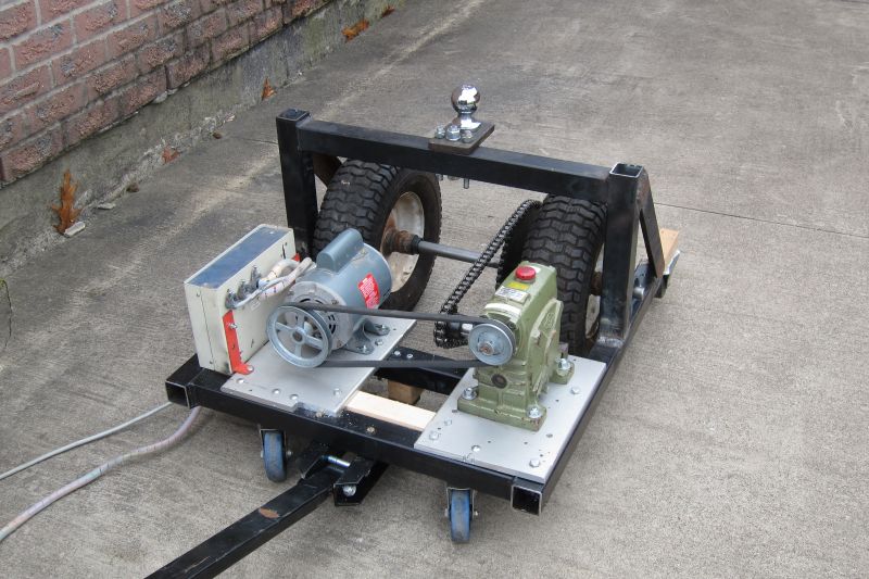
Two 4″ swivel casters (actually 5″ in height from ground to metal mounting plate) were mounted under the unit and secured to the metal frame with bolts. These casters carry the weight of the unit (motor side) and allow the unit to be swiveled to steer it.
A chain connects the 11″ sprocket on the main 1″ shaft to the output shaft of a 100:1 gear reducer onto which a 3″ sprocket was mounted. The gear reducer is quite heavy being made of cast iron and is oil filled. It was bolted onto a 9″ wide by 10″ long piece of 1/2″ thick aluminum plate which was then bolted onto the main frame with four 5/16″ bolts. Finally, a 1/2hp motor was bolted onto another piece of aluminum mounted beside the gear reducer and connected by a V belt.
The motor is a capacitor-start type with a high start-up torque and is reversible. It is controlled by a modified three-phase reversing contactor which switches the phase of one internal coil with respect to the main motor coil to reverse it. The contactor also allows latched operation if desired. Of course such an arrangement is not required as a simple motor reversing switch could be used however use of this contactor allows low-current control of the motor (i.e. small switches embedded right into the handle with a “stop on release” function).
The motor runs at 1725rpm which is reduced via the 5″ pulley on it (and the 3″ pulley on the gear reducer) to 1035rpm. The output of the 100:1 gear reducer is then 10.35rpm reduced further by the sprockets (3″ on the reducer output and 11″ on the main shaft) to 2.8rpm. The 16″ diameter tire has a circumference of 50″ and hence runs 141″ of travel per minute or about 2.3 inches per second. Should a different speed be desired, the pulleys on the motor could easily be reversed or changed entirely to different sizes.
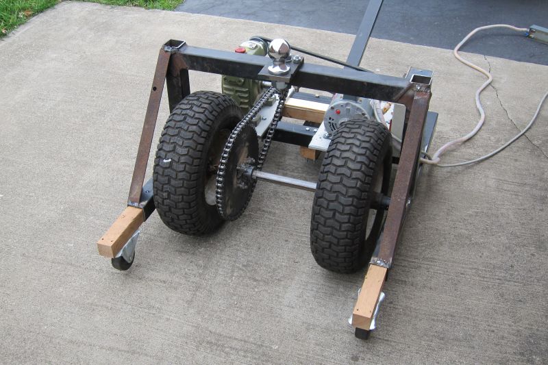
Finally, two casters were mounted on pieces of white oak inserted into the open ends of the frame. These casters are used as “wheelie bars” and will prevent the unit from tipping should an obstruction on the ground stop a wheel from moving … they might not be required but are there “just in case”.
All welds were made with a DC fluxcore MIG (gasless) at 105A of current using 0.030″ wire. As nothing was particularly critical, the only tools required (other than a welder) were an abrasive cut-off saw, a drill press (with some very large diameter drills), a hand-drill (for drilling holes to bolt the motor and reducer mounts to the frame – required since the welded unit was far too heavy not to mention unwieldy to put onto the drill press), and a grinder to clean-up before and after welds and cuts. I might mention that drilling those holes by hand was an awful job and some forethought would have allowed them to be drilled on the drill press beforehand (i.e. drilling ALL holes into the main frame before welding the ball-carrier onto the top).
Bill Of Materials
- 2″ square steel tubing cut into lengths (2*31″, 3*25″, 2*13.5″)
- Two pieces of angle steel, 17″ long (braces for the ball mount)
- Two tires 16*6.50-8
- Four 1″ hubs with keyways for the above tires
- Two 1″ pillow block bearings
- 29″ of 1″ keyed shaft
- 11″ sprocket (50×54)
- 1″ keyed hub for the above sprocket (weld-on)
- 3″ sprocket (50×13)
- 1″ keyed hub for the above sprocket (weld-on)
- Four 1″ shaft collars (to prevent shaft from moving side-to-side)
- #50 chain plus one full link and a half-link to join as required
- Two Aluminum plates, 9″ by 10″
- 100:1 gear reducer (cast, input able to run at 2000 rpm)
- Half horsepower reversible AC motor, capacitor start
- 3″ and 5″ pulleys (one for motor, one for gearbox)
- V-belt
- 2 5/16″ trailer ball
- Two 4″ swivel casters (these are actually 5″ from ground to top plate)
A short video of the unit in operation can be viewed here:
The unit has been used for several years to move our Grand Design Imagine 2800BH in and out of the yard. This 7000 lb trailer moves well on the dolly. Breakaway torque is so high that with 1000lb of tongue weight on the dolly the drive tire will spin (leaving a rubber mark on the concrete) should a trailer tire become blocked … no stalling of the motor!