This page dedicated to electromechanical telephone switching technologies including a magical little switch designed by a Funeral director that gave us user dialing.
During the early days of telephones one pair of wires was required to route signals from each individual telephone to a central office where multitudes of operators routed calls from the calling party to the destination. In some areas, a single wire and a ground return were used. Users cranked a handle on the telephone which triggered an indicator for the calling line and rang a bell or buzzer, on the switchboard in the central office. An operator then plugged a switchboard cord connecting a headset to the incoming line and asked for a “number please” at which point she (operators were usually women in those days) would make a connection between the lines with jacks and ring the destination line: the user, or operator, would crank their telephone again to generate a ringing signal at the called party’s telephone set. This system was labour intensive as well as prone to abuse: legend has it that in 1889 an undertaker in Kansas named Almon Strowger suspected a local telephone operator was routing business away from his funeral parlour to his only competition, the husband of the operator. Born was a ‘man on a mission’ bent on developing a switching system to replace operators by allowing user-directed calls without intervention. His invention changed the world ….
Uniselector Switches
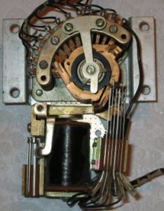 We begin with a look at a single-axis stepping relay switch (in telecomm, called a ‘switch’, but in other applications such as old pinball machines, which also used these for counting, called a ‘relay’) . Such a switch may be used to allow a subscriber dialing a telephone to select one of ten lines as follows: When the subscriber dials the telephone a series of electrical pulses are generated on the line (at a maximum rate of ten per second). Each pulse causes the rotor (which starts at the ‘home’ position) to be advanced by one step. If each set of ten contacts on the switch connect to a telephone set the system allows the user to direct-dial up to ten telephones directly.
In theory, the system could be expanded by placing ten more switches in series with each of the ten contacts from the first switches – when a pause between dialing pulses is sensed the system would transfer the next set of pulses to the second switch.
In all, eleven rotary switches would be required to select any one of a hundred extensions. The problem with this scheme is one of numbers with an enormous quantity of switches required as the number of telephones in the system increases. As well, each subscriber telephone would require a similar set of switches in order to be able to dial and connect to any other on the system.
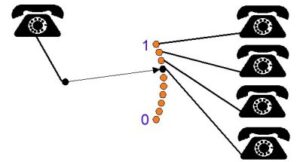 In operation, a uniselector would count the number of dialing pulses from the incoming line and step the contacts in a rotary manner that number of steps. The calling party is then connected to one of ten possible destination lines. Obviously the system is quite limited in terms of number of extensions however it is possible to expand it by cascading multiple switches of this type (multiple meaning an enormous number would be required for even a small exchange employing, say, five-digit phone numbers.
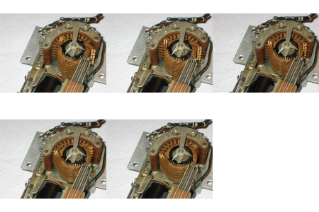 A Unistep switch operating. Visible in the animation is the rotor stepping through several contacts. This particular switch features a number of rows of contacts. While some stepping switches feature two coils (one to advance the contacts forward and another to reset the contacts to the ‘home’ position this switch has only one coil. To reset the switch to the starting position it is advanced repeatedly until a set of contacts on top of the switch is closed.
Two-axis (Strowger) Switches
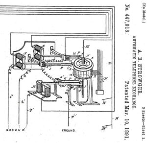 In operation, switches were housed in cans and mounted on racks. The actual motion of the switch is in two axes: the switch can step in an up/down direction (or rather up and ‘reset to home’ position) as well as in a rotary direction like the uniselector above.
The actual switch contains three electromagnetic coils: one to step the switch Upwards to the next deck of contacts, one to rotate the contacts one position right on the deck of contacts, and a third to reset the entire switch to the ‘home’ position in which the contacts rotate completely to the left and drop to the bottom of the deck.
Switching Mechanism (Trunking)
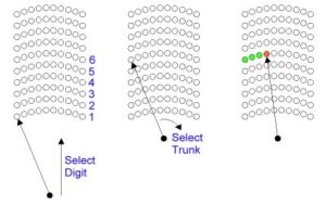 A single two-axis Strowger switch can be used to replace the eleven switches of the previous example (one for the first digit and ten for the second digit) by simply using the first set of dialing pulses to step the switch upwards to a bank of contacts then using the second set of pulses to rotate the contacts to the destination line. In this respect, the switch resembles a stack of ten uniselector-type switches.
A more efficient use of these switches involves the use of trunking in which dialing pulses step the wipers upwards after which a circuit attached to the switch automatically rotates the contacts until a free trunk line connecting this switch to the next is found. In the example above the digit ‘6’ is dialed which causes the contacts to step up six levels at which point the wipers rotate repeatedly until a free trunk line is found connecting it to the next switch (which in turn handles the next digit dialed). In the above example the first three trunk lines (green contacts) are already in use and so unavailable until the fourth trunk line (free, in red) is located at which point the incoming line is connected to this output.
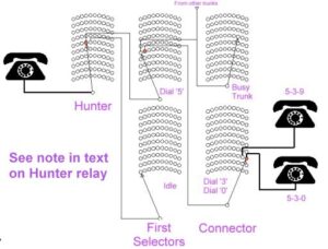 Continuing with the analysis of trunking the above example shows a three-number exchange (this is exactly what the town I live-in had during the early part of the last century as I’ve seen early advertisements with three-digit phone numbers). The first Strowger switch on the left is a rotary ‘hunter’ switch which looks for an off-hook telephone placing a call. When a phone is taken off the hook the line voltage (normally 48 volts) drops to about 12 volts. A selector hunter rotary switch sweeps across all incoming lines until a ground, indicating an off-hook line is found, it establishes a connection to the next switch, a selector which provides dialtone, and actually handles the first digit. In the case of this example, both selectors are free in this example and so the first one (top) is chosen. The subscriber then dials the first digit ‘5’ at which point the selector steps UP five levels. There is a pause between dialed digits now during which the switch rotates to find the next free selector in the chain … in this example the second selector (called a connector as we shall see) is busy so the next on in the chain (bottom right) is selected. There can be any number of selectors in the chain – for a five-digit dialing scheme there would be three sets of selectors. However if all digits are not required, in some offices selectors can be set to absorb digits.
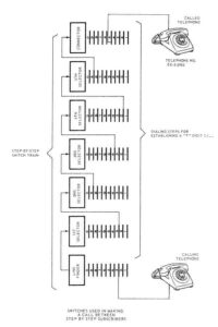 The complete switch chain for a seven-digit system may be seen here – it will help clarify the arrangement of switches in the system. The final selector is called a connector and handles the last two digits dialed. In the example above the second digit dialed was a three so the third contact level is selected. Finally the last digit causes the switch to rotate that number of steps to find the final destination. Only connectors handle two digits.
As you can see, there are three configurations of switches in the system: hunter selectors (the ‘front-line’ switches), selectors (of which there will be more than any other switches in the system), and connectors (which handle the final connection and also handle two digits of the number).
Now, as one reader noted, the arrangement of the Hunter is one in which each subscriber line required one hunter selector switch – the incoming line is then routed to one of ten trunks to the first selector. This is OK for a small number of lines and was indeed a methodology used by some systems during the early 1900’s however when several thousand lines are employed, the complexity of providing each line with a switch becomes prohibitive. An improved system whereby the first switches are ‘Line Finders’ was developed: at first plunger types, then rotary. These switches constantly seek calling circuits, connecting such a circuit to an idle selector so the selection process can continue as above.
And so, Strowger switches come in three variations: linefinders, selectors (the most plentiful in a system), and connectors. In a typical system, for every 200 incoming lines there are about 20 linefinders. Linefinders are identified by three banks of 100 terminals each underneath. A start circuit is used to step up and rotate to find a live terminal. Selectors are then used to select each digit except for the last two digits which are routed by a connector. Selectors feature two banks of terminals underneath, the top bank 100 incoming two-wire trunks and the bottom bank control contacts. First selectors are special in that they provide dial tone. The top bank of contacts (accessed when ten pulses are counted – that is, when a zero is dialed as the first digit) routes an incoming call to the operator and the bottom bank (accessed when a one is dialed and a single pulse is counted) routes calls to special services such as long distance. Rotation of the switch then routes the call to a trunk to the next (second) selector. In the event that any selector switch rotates too far without finding a free trunk to the next selector, a switch on the rotary shaft closes signifying ‘trunk busy’ – only selectors have these contacts. Finally, a connector handles the last two digits: vertical (up/down) motion on the second-to-last digit and horizontal (rotary) motion on the last digit. Connectors feature similar contact banks to selectors except each terminal now connects directly to a subscriber line. Connectors also handle special functions such as checking for a busy line and, if the line is free, applying a ring signal. In summary, a call on a normal seven-digit system would be routed from a subscriber’s (calling) line by a linefinder, through five selectors (one for each of the first five digits dialed) and finally via a single connector which handles the last two digits dialed, connecting to the called line.
 My particular strowger switch is a selector: two sets of contacts are attached to the rotating shaft and the shaft features a ‘trunk busy’ set of contacts. Five horizontal relays are on the top of the unit in positions A,B,C,E, and F. One relay (A) has two coil windings and the relay at position C has a copper ring on the heel for a delay (see left for the use of those relays – click on the image for a larger view).
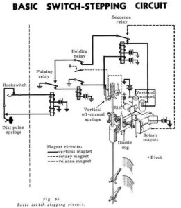
Although one would never connect a dial directly to a connector, the diagram above (from the 1950’s guide “Electrical Principles of Telephony”, Bulletin 800, produced by Automatic Electric, a subsidiary of General Telephone and Electronics) describes quite well how a Strowger switch operates. Upon lifting the receiver, the subscriber’s telephone closes the line circuit and pulls the pulsing relay in. In turn, the holding relay and the sequence relays also operate. Let us now assume the caller dials “3-4”. The first number, 3, generates three quick pulses on the pulsing relay (a fast-acting relay). Although this breaks the circuit to the holding relay, that relay has a copper sleeve on the heel which causes it to hold down for about one-third of a second so during the pulse train it stays pulled-in. Each time the pulsing relay operates pulses are sent through the holding and sequence relay contacts to the vertical magnets causing the strowger switch to step upwards three pulses to the third bank-contact level. The sequence relay also features a copper collar and so stays pulled-in during the pulse stream.
After the stream of three pulses is complete, the holding relay stays pulled-in however current is no longer supplied to the sequence relay and so after a short time interval, the sequence relay releases. Now, the user dials “4”. Pulses are now routed from the pulsing relay through the holding relay but this time the sequence relay is released and so pulses are fed to the rotary magnet causing the wiper to rotate across the contacts by four steps. Line 34 is now selected by the Strowger switch. When the caller releases the line the line circuit is opened and the holding relay releases. With the release magnet now operated the shaft rotates (via a spring at the top of the shaft) to the home position and the wiper falls by gravity to the lowest position.
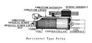 Selectors would feature another slow-to-release sequence relay to detect the end of a digit dialed and route the pulse stream to the next selector in the chain. Routing of the digits between the two axes then, and in a system between two successive relays, requires time-delay relays (as illustrated above). For use in telephone system, developed long before the days of semiconductors, ingeniously-simple relays were developed which featured copper collars which built-up currents (acting like a low-impedance secondary winding of a transformer) and delayed action of the relay, either slow-to-release or slow-to-act. Such a relay is illustrated right.
Relays may act as slow operating or slow releasing. Where a copper collar is mounted on the armature end of a relay – application of a current to the relay coil causes the copper collar to build-up a field opposite to that of the coil. This field gradually dies-away and eventually the relay pulls-in (after a delay). Where a copper collar is mounted at the heel of the relay, when current is removed it produces a field in the same direction as the original coil did – it eventually dies-away but in doing so holds the relay closed longer than normal. A slow releasing relay is located on the top of my switch.
Mechanicals
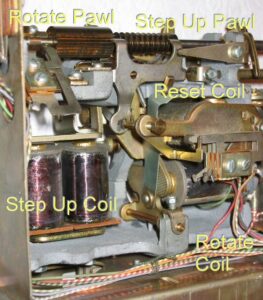 The three electromagnetic coils are evident in the photo as well as the two ratchet mechanisms (one rotary, the other linear for the ‘step-up’ motion). Impulses on the ‘up’ coil cause a pawl in the switch to push upwards on the ratchet moving the shaft (with external contacts) upwards.
A similar motion causes another pawl to ratchet the shaft in a rotating motion. When energized, the reset coil releases both ratchet mechanisms allowing the shaft to rotate to the ‘home’ position (via a spring) and drop below the lowest contact deck.
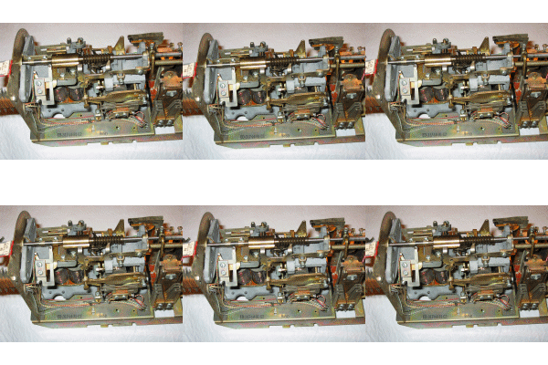 An animation of a switch stepping in the ‘up’ direction. In this case electrical pulses were applied to the ‘step-up’ coil only. Only ten steps are possible in this direction – if this is a selector, each pulse corresponds to a digit dialed.
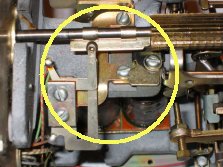 …and back to the trunking system, what happens is a selector switch rotates full-circle and still can’t find a free trunk line to connect it to the next selector in the chain?? After stepping beyond the contacts a protrusion on the shaft closes another set of contacts which then connects a ‘busy trunk’ signal generator to the calling line to indicate all trunks are busy (this is different from a normal ‘busy’ tone).
I was told switches of this type required a good bit of maintenance about twice a year including alignment of various switch contacts, adjustment of the relays (delay time could be set by adjusting slugs on the relay), and lubrication of all moving parts. It surprises me, personally, that the telephone network was so reliable given the mechanical complexities involved but simple electromechanical solutions such as the delay relay solve what would otherwise have been a complex problem.
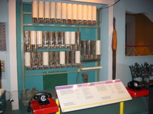 A demonstration system at the Canadian Science and Technology Museum in Ottawa, Ontario. The system features a rack of switches wired to allow two telephones to connect together when the correct number is dialed. Visitors can observe linefinder as well as selector switches operating as the number is dialed. Click on the image for a larger version – the linefinders are visible in the middle row of switches at either end (the switches with three banks of contacts).