Described is an interface allowing a phone app to remotely control a DSC 1500 alarm panel. The alarm status (armed/disarmed) can be read remotely and the alarm can be remotely armed/disarmed.
Introduction
The project consists of two elements: first, an interface to an app-based control system such that activating a device generates a signal to arm or disarm the panel and second, an interface to the DSC 1500 alarm panel which emulates a KeyBus keypad which allows both monitoring of status (armed, ready, etc) and sending keystrokes to the panel.
It would be nice to built a phone-based app from scratch however a far easier route is to use a commercially-available smart AC switch (a Kasa HS-200), modified so that it produces an arm/disarm signal and can be controlled from the alarm system (so that when a user in the house arms or disarms the system using the keypad the switch accurately reflects the system status. As such, the phone app will show a device called ‘Alarm’ … it will always reflect the status of the system in the house – so when the alarm is armed the switch will always show ‘on’ – and allow the user to arm/disarm remotely by turning the device on or off with the app.
Interfacing with the Kasa AC Switch
WARNING: The logic power for the switch is derived directly from the AC line so it is absolutely necessary to opto-isolate all signal to/from the switch without exception. All wiring to the switch (including the logic ground and +5V lines) is ‘hot’ and cannot be connected directly to ANY circuit outside the switch.
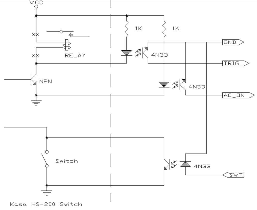
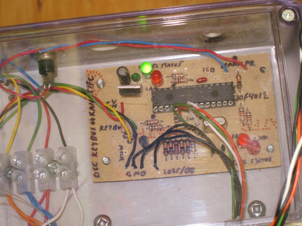
The Kasa switch was disassembled and the relay (5V SPST) removed. Wires that originally went to the relay coil (one to +5V and one to an NPN transistor – red and blue in the photos below, respectively) were run to the LED of a 4N33 opto-isolator through a series resistor. When the Kasa switch turns on, the opto-isolator is wired to produce an active-low output for the microcontroller (/Trigger). When this output goes high the relay is unenergized (i.e. the load is off) however to be valid one must also ascertain that the AC power is on – easily done with a second opto-isolator (/AC_ON) connected to the +5V line and ground (red and black) on the switch. Finally, the interface must be able to control the switch. If, for example, the user turns on the alarm but the panel cannot do so (e.g. not ready due to an open door or window) the interface can toggle the switch to the off state (and in doing so, the user can see, via the app that the switch is off and the alarm is not armed. This is accomplished by a third 4N33 wired so that the output darlington transistor is across the original switch (orange and black). The modified switch, then, has four interface wires all optoisolated from the live parts of the switch.
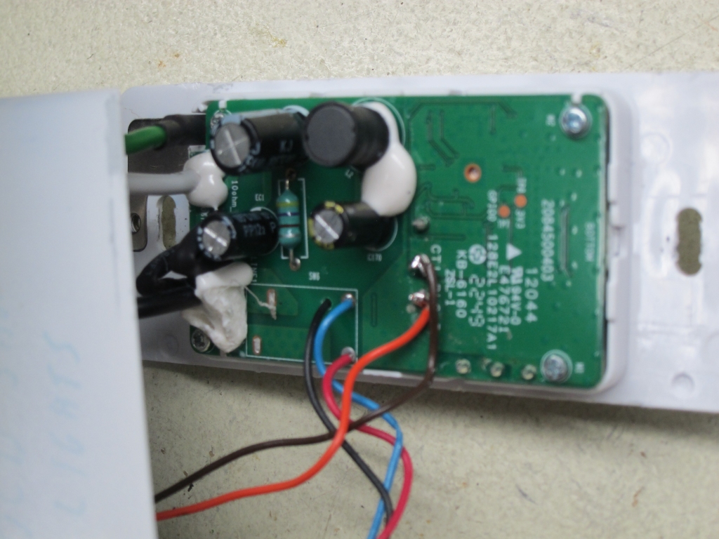
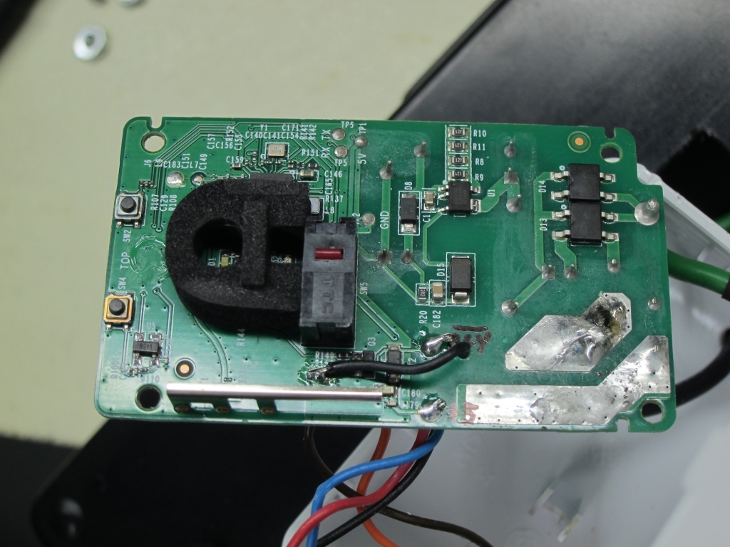
Two photos of the insides of the HS-200 switch. The left photo shows the rear of the PC board with the relay removed and with wires connecting to the coil connections and the microswitch for the paddle. The right photo shows the front of the PC board – the black wire connects to the ground (-) terminal for the optoisolator which indicates power is on.
KeyBus Interface
Keybus is a simple protocol used by DSC alarm panels to communicate with PC1550 “classic six zone” keypads. The clock line remains high for 20-30ms after which the alarm panel produces a stream of sixteen clock pulses. When the clock pulse is high, the data line reflects a bit representing an open zone and alarm status (armed, ready, etc). When the clock pulse is low, a bit is asserted on the data line to represent a keypress (although only seven bits are sent which represent the keypad row and column of the switch pressed). The data line floats high (logic zero) and is pulled low to assert a logic high state.
The algorithm use here is simple. An interrupt occurs on every clock edge (low -> high or high -> low). If the clock is high, a bit is read into a register (which shifts one bit each time) until sixteen clocks are received. The received word is as follows:
Z1,Z2,Z3,Z4,Z5,Z6,X,X,Rdy,Arm,Mem,Byp,Trb,X,X,Beep
where Z1-Z6 are the six sensor zones, X is an unused bit, Rdy indicates the alarm is ready to arm, Arm indicates the alarm is currently armed, Mem indicates Memory, Byp indicates a zone is bypassed, Trb indicates Trouble, and Beep causes the keypad to emit a tone. Most of these bits are represented by LEDs on the keypad.
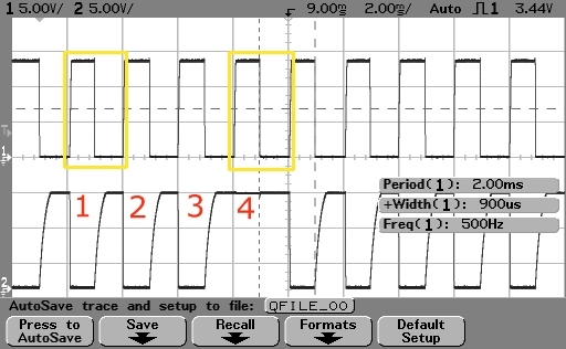 The scope shot to the left, with the clock in the upper trace and the data on the lower trace, shows Zone 4 open. In the ‘normal’ state with all zones closed the alarm is in a Ready state so only the ninth bit is high (not here as the open zone prevents arming).
If, on interrupt, the clock is low, a bit is sent only if there is a key in the buffer to send. The first bit is logic 0 (high) followed by seven bits which represent the column (first three bits, as 001 – 100) and row (next four bits, as 0001 – 1000) of a pressed key. So, a “1” key is sent as:
0 100 0001 which means column 1 and row 1. A “2” key would be column 2 and row 1, etc.
In addition to the external edge interrupt, timers are used to determine if link is lost (>30ms with no clock detected which generates an interrupt) and if a start bit is encountered (no clock for >20ms but <30ms).
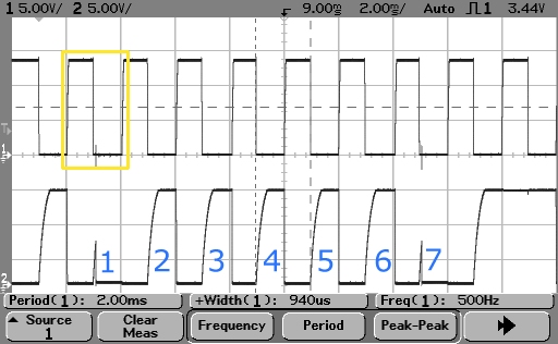 This scope shot shows a “1” key pressed. Aside from the bits for the keypress the status bits are also shown: in this case all zones are closed (off) and the alarm is ready hence the ninth status bit is high (for the ready LED).
It is important to know the panel status as the smart switch must be set to the actual state (i.e. off if disarmed and on if armed) and cannot be armed unless the alarm is in the ready state.
Main System
Although the Microchip 18F family is more than adequate for the task, it has a single interrupt vector and an interrupt-on-change for port B while the 30F family is overkill but more convenient to use since it has vectored interrupts (of which at least three will be used) as well as a the ability to detect an edge (both L->H or H->L on a single I/O pin). Of course ‘complete overkill’ would be a dual-core 33FJ processor but let’s go with the 30F for now. The dsPIC30F4012 fits the bill nicely: 28-pins, EEPROM on chip (to store passcodes for the system), 5V compatibility, and all the niceties of the 30F family including vectored interrupts.
The I/O pins of the microcontroller are assigned as follows:
RB0 input Keybus CLK input (interrupt on change)
RB1 input Keybus DATA input
RB2 output Keybus DATA transmit (pulls the DATA line low)
RB3 input ARM Trigger from Kasa Interface (active low)
RB4 input AC On signal from Kasa Interface (active low)
RB5 output Toggle Kasa switch state
RD0 output Heartbeat/Link OK LED
RD1 output Command Fault LED
RE0 output READY LED state indicator
RE1 output ARMED LED state indicator
RE8 input Learn Pushbutton
Keybus operates at voltage levels of ground to +12V and so two resistors (15K in series, 10K to ground) are used to divide this down to 0 to +5V for the inputs of the microcontroller. The Data line must also be pulled to ground using an NPN transistor to assert a low level (it floats high). The 5V supply for the microcontroller is derived from the Keybus power lines via a simple 7805 linear regulator … current consumption is under 20mA for the entire board including LEDs (which have 1K series resistors to reduce current).
Two interrupts are used for the Keybus communications subsystem: a change-on-edge interrupt connected to the clock line and a timer which interrupts after 30ms have elapsed. On a change interrupt the ISR checks if 20ms has elapsed using a second timer) – if it has this is the start of a new data word. If less than 20ms has elapsed it is in the middle of a data word. The clock polarity is then checked – if low and there is something to send in the buffer register, a single bit is clocked out via the data line (which floats high and is pulled low using an NPN transistor). If the clock line is high, a single bit is received and shifted to assemble an incoming word for a total of sixteen bits. The state of the data line is actually sampled 100 microseconds after the clock edge allowing it to settle (a technique used in almost all UARTs).
The 30ms timer interrupt is used to determine if a link error has occurred – if 30ms elapses without a change interrupt being detected the clock is lost and the link to Keybus has failed (or the alarm panel has died, but either way the system won’t work).
The main data to extract from the received word is is the alarm status (armed / disarmed, so that the switch can be set to reflect the current status) and ready status (since the alarm can only be armed if the panel is ready). The main program loop is responsible for updating the switch as required as well as obtaining keystrokes in learn mode (for storage in on-chip EEPROM) and sending keystrokes to the panel to arm/disarm it as required.
The Code for the project can be found in the file DscInterfaceCode (renamed to “.txt” but in reality a “.s” source file for use with MPLAB X). Definitely not the best piece of code I’ve ever written (in fact it could be described as ‘quick and dirty’) but it works reliably. Even if you’re not using it, specifically, for a DSC alarm panel interface you might be able to use the code which interfaces to the Kasa switch.